I was wondering about this in the GRBL 1.1f congig file. Since the K40 fires on low and off on high, is this what to use instead of having a logic switching circuit? I am using the Protoneer CNC Arduino shield.
// Inverts the spindle enable pin from low-disabled/high-enabled to low-enabled/high-disabled. Useful
// for some pre-built electronic boards.
// NOTE: If VARIABLE_SPINDLE is enabled(default), this option has no effect as the PWM output and
// spindle enable are combined to one pin. If you need both this option and spindle speed PWM,
// uncomment the config option USE_SPINDLE_DIR_AS_ENABLE_PIN below.
// #define INVERT_SPINDLE_ENABLE_PIN // Default disabled. Uncomment to enable.
// By default on a 328p(Uno), Grbl combines the variable spindle PWM and the enable into one pin to help
// preserve I/O pins. For certain setups, these may need to be separate pins. This configure option uses
// the spindle direction pin(D13) as a separate spindle enable pin along with spindle speed PWM on pin D11.
// NOTE: This configure option only works with VARIABLE_SPINDLE enabled and a 328p processor (Uno).
// NOTE: Without a direction pin, M4 will not have a pin output to indicate a difference with M3.
// NOTE: BEWARE! The Arduino bootloader toggles the D13 pin when it powers up. If you flash Grbl with
// a programmer (you can use a spare Arduino as “Arduino as ISP”. Search the web on how to wire this.),
// this D13 LED toggling should go away. We haven’t tested this though. Please report how it goes!
// #define USE_SPINDLE_DIR_AS_ENABLE_PIN // Default disabled. Uncomment to enable.
On a laser, you want to use variable spindle (PWM) to adjust the laser power, but in this case the INVERT_SPINDLE_ENABLE_PIN has no effect.
You could either change the cabling to use TH (active high) instead of LO (active low) of your K40 power supply or you could invert the PWM output with a mosfet or transistor.
@cprezzi , Thank you for the reply! So I should keep the config “stock” besides parameters that are needed for proper machine movement and just trigger $32=1 for laser control and use the Mosfet to invert? Any insight on how to connect the CNC shield for proper K40 control?
The K40 power supply has an internal pull up resistor on the L input, which only needs to be tied to GND to fire the laser.
This means you could directly connect an N-Channel MOSFETs drain pin to the L input of the power supply, the source to GND and the gate to the PWM output of the arduino. GND of Adruino and power supply need to be connected also.
Normaly the IN pin is connected to a potentiometer to adjust the max current (= laser power) and the L pin is used for PWM (low active).
So I would connect the mosfet drain to the L pin without an additional pullup (because L is pulled up internally in the PSU).
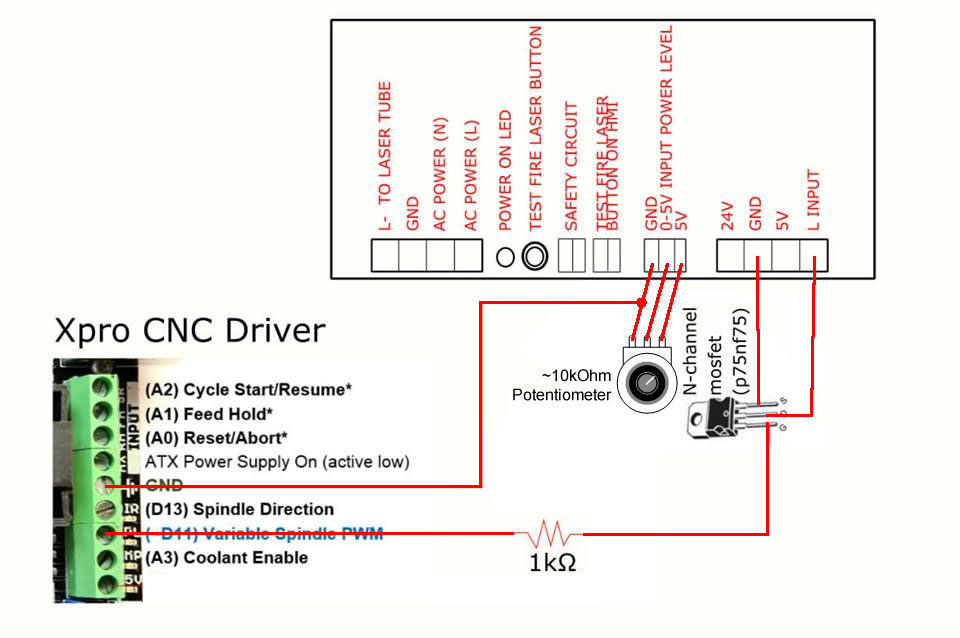
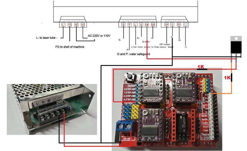
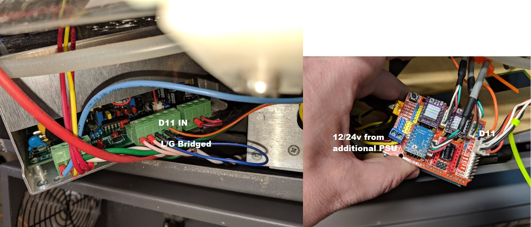
@cprezzi So like this or using the L on the center connector? A bud of mine is using the same controller without FET and has the L/G bridged (center connector) and has D11 to the 0-5v connection also on the center connector. His works fine and PWM is controlled by shield/Software BUT, he does have a certain way to power the board or he gets a prefire of laser which I am trying to avoid. That is why I wanted to add the FET to eliminate that. I am being told NUMEROUS ways to wire this up to a K40 and my head hurts… LOL
@Custom_Creations Your schematics is close, but you don’t need the resistor and connection to 5V on the Xpro, because the Laser PSU has an internal pullup.
@cprezzi I do not have an xpro. Just example of connection So take off the resistor on the 5v connection and it will be correct or dont use the 5v and resistor at all??
The advantage of having a potentiometer is that you can adjust the maximum power with the pot and still use the whole PWM range of 0-100%. This way you don’t lose grayscale resolution.
Yes. You could just bridge the center (input power level) to the right (5V) pin to fix power to max. Or better use a fixed voltage divider to set the max. allowed current. But I don’t recomend both.
Grbl has only 256 PWM steps from 0 to 100%. If you just need 10% power for the darkest part of an engrave, then there are only 25 different power levels left. That’s not enough for grayscale.
Ciao @cprezzi sto cercando di collegare CNC shield al PSU del K40. La cnc shield è alimentata da un alimentatore aggiuntivo. Non riesco a capire cosa sbaglio, il pwm non funziona. Per favore potresti aiutarmi?
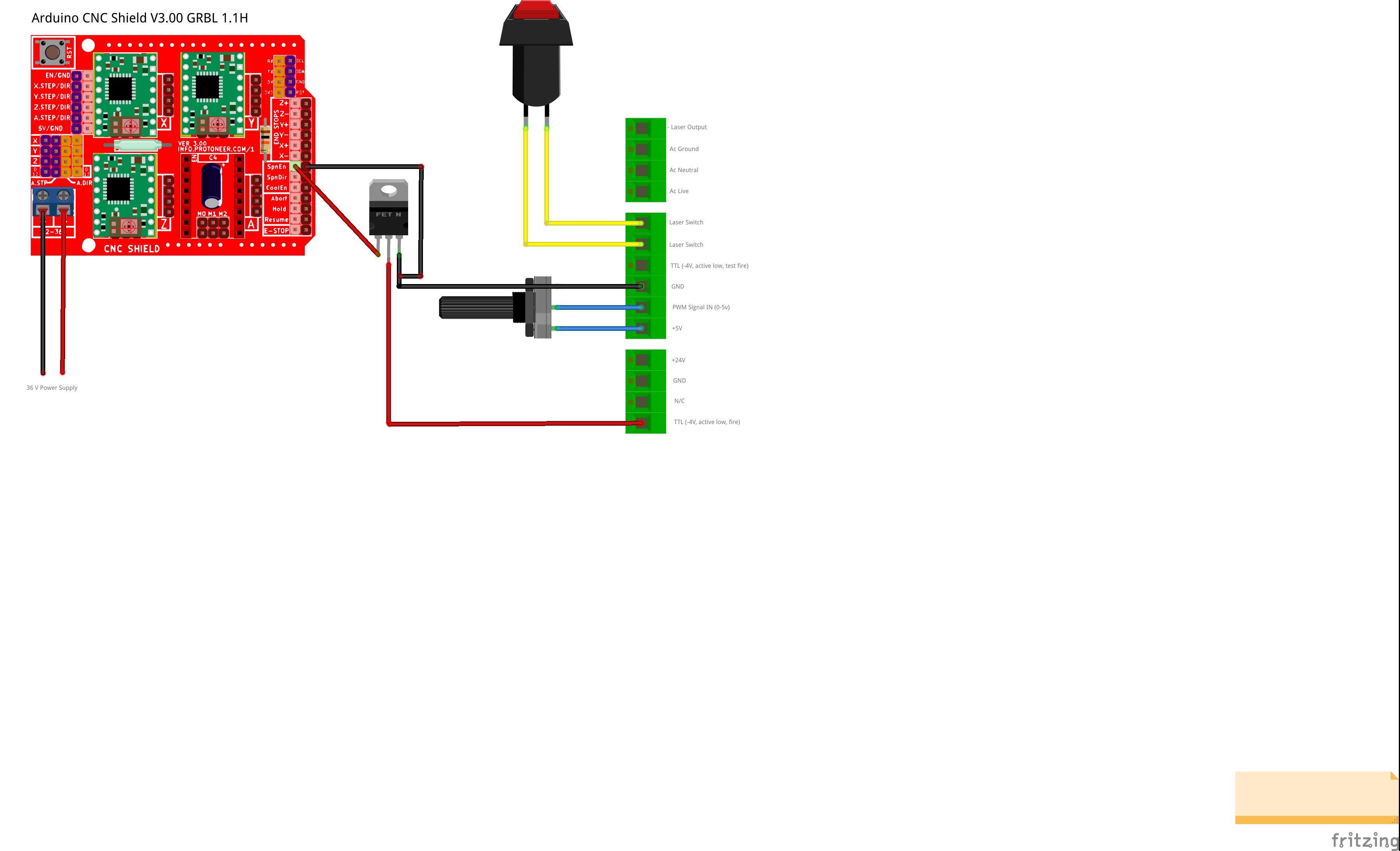
I’m sorry, my italien is very bad. I would suggest to leave the potentiometer of the K40 connected to GND, IN and 5V of the PSU (to set the maximum power) and use the TTL (active low) pin for the PWM signal of the CNC shield (usually on SpnEn).
A small problem is, that the PSU needs an inverted signal on the TTL pin. So you need to invert the PWM signal of the CNC shield. This could be done with a NPN-Transistor or N-Channel MOSFET: https://www.quora.com/How-is-MOSFET-used-as-an-inverter
For this to work, the GNDs of the CNC Shield and PSU needs to be connected too.
Hi @cprezzi, Thanks for your suggestions. Sorry for my English
I modified my scheme by inserting an N-Channel Mosfet and the potentiometer. Is it correct now? I forgot to say that I am using Grbl 1.1F, so using SpnEn Pin is the greyscale preserved (or i need to use Z+ pin)?
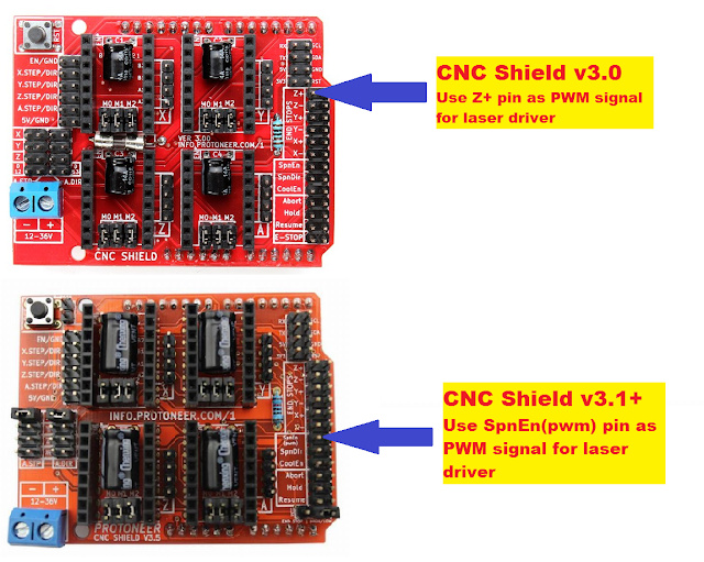
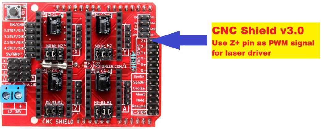
If your CNC Shield is the older version V3.0, you need to use Z+ insted of SpnEn.
On CNC Shield V3.1 the pins was swapped, so you could use SpnEn(pwm) pin.
Hi @cprezzi, thank you very much. Do you recommend using a 1k ohm resistance between Z+ and mosfet? Also, I am unable to find a p75nf75 mosfet, is there an alternative?

 So take off the resistor on the 5v connection and it will be correct or dont use the 5v and resistor at all??