I may be missing something obvious, but is it possible to move/offset gcode objects around in the Chilipeppr 3D space.
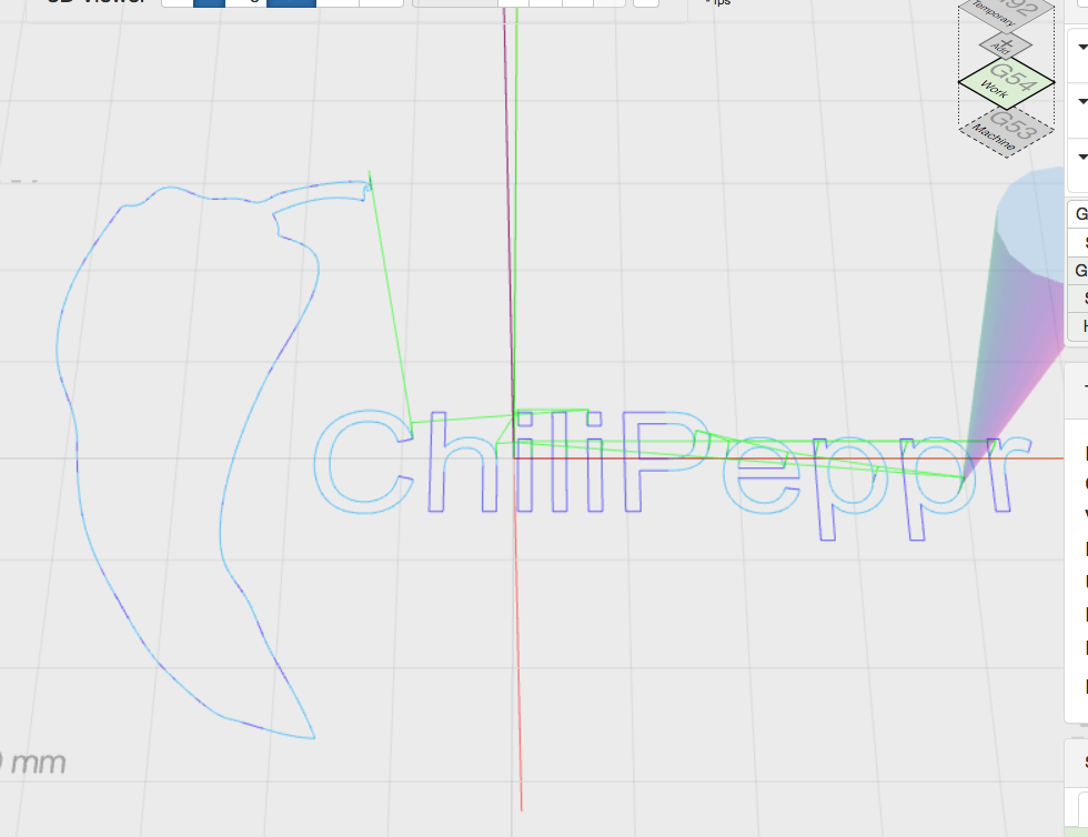
For example, if my machine is homed and I try and run the default/test Chilipeppr mm logo, 0,0,0 is in the middle of the logo and within a few commands, it trips my limit switch.
Line 11 of the logo code is: N11 G0 X39.2659 Y-3.4776 which is the line that tries to send my carriage to negative space.
This isn’t a problem with the demo itself - but how to offset models that have their origin at a different place from 0,0
I guess it’s not a serious problem, as I will be generating my own gcode, but I was interested in how to cope with a situation where a model was built with an unusual origin.
A workaround:
Type im the console: G28.3 X-50 Y-50 to change machine coordinates without gantry moving.
My very first CNC cut long time ago was a CP logo, unfortunately with no limit switches installed. IT was a plywood based machine with ball screws and I still remember the sounds.
I think this would be better to have the logo positioned in the positive X/Y quarter and not centered in relation to (0,0) to avoid crashing issues. This will also help CNC newbies not to learn the hard way, I did. @jlauer do you see any chance to update logo positioning on the default CP page(s)?
There is no “standard” among graphics/CAD design tools as to where in the X-Y space models are authored. For tinyG users, the default G55 coordinate system is offset from G54 (0,0) by (Xmax/2,Ymax/2), but that is tinyG specific.
Keep in mind that many DYI machines do not have limit switches or homing cycles.
The more I’ve machined, the more I set the 0,0 in the lower left corner, so yeah, that CP logo is odd to have the 0,0 in the center. It’s not a bad idea to get a different default logo in there.
This is what G28.3 XYZ is doing. This command will change coordinates per axis without gantry moving. Only enter values for axis you want to change the coordinates.