I have troubles understanding the consumption of a single ws2813 5m stripe.

I have troubles understanding the consumption of a single ws2813 5m stripe.
I want to connect 5m of ws2813 led strip (5v), with 60leds per meter. My calculation is that it will make 5m * 60leds/m * 60mA/led = 18A.
Is this correct !?! so I would need a 20A transformer (220v to 5v) !? isnt that huge ?
1- is there any way to reduce this (parallel wiring? if so, can i still control all the leds as i wish?)
2- i would need a 2.5mm² wire, right ? i would solder it between the transformer and the led strip, and would also use this between my wall and the transformer, correct ?
3- can the arduino handle the 20A ?! the 2.5mm² ground and 5v power will also go to the arduino, and the data cable (lot less than 2.5mm² i believe) as well, no issue for the arduino ?

thank you for your help ! im really surprised by the 20A, looks like its gonna get hot in there !

That’s the max current draw, at max brightness, solid white. You can use FastLED’s power management to limit current draw. https://github.com/FastLED/FastLED/wiki/Power-notes#managing-power-in-fastled
https://github.com/FastLED/FastLED/wiki/Power-notes#managing-power-in-fastled

You could then use a much smaller power supply, smaller wiring, etc.

Here’s a few answers to the best of my knowledge and understanding of your questions…

  1. No… there is no wiring trick that will achieve this.

  2. No… to my understanding, no transformer will do what you need. You will need a 5V power supply. The required wire gauge will depend on the length of the wire, the maximum current draw AND the allowable voltage drop. No single answer for this. Assuming a 220VAC to 5VDC PSU, the wiring size to the PSU 220V AC input will not require a heavy gauge like the one on the 5V DC output.

  3. No… The Arduino is not required to handle the 20 Amps. It definitely can handle the data for 600 RGB LEDs though. As long as it has enough memory (The Arduino UNO would not work here, not enough memory). Yes… The data wiring can be very small.

As Jason explained, IF you will have all your LED set to full brightness white, then yes, a 5VDC 20 Amps PSU will be required for that many LEDS.

I bought a ws2812 strip that only consumed 40mA per each full lit. Go measure your actual led strip, may be you can lower your calculations about one or another amperes…

A 1,5mm² will do probably too, if the total length will stay below a certain value (<5m may be). The minimum supply voltage of a ws2812 is 3,5V, so some voltage drop is tolerable.

Very important: At 5m strip length you need at least 4 better 5 points in equal distances to feed power to the strip. Attaching the power only at one end of the strip will not work. In that case the distant end of will be dim lit, in worst case the strip can catch on fire!

On the other hand, if you use 5 supply points, each wire only needs to have 1/5 of cross sectional area = 0,3mm²

5V * 20A = 100W. Don’t forget about that your setup will generate quite a lot of heat, mostly the strip itself. This is equivalent to a stove plate on lowest setting or a good soldering iron. Most budget power supplies are adjustable ±0,5V. Adjust it to 4,5V to reduce heat dissipation by a good amount.

thank you all for your answers.

@Jason_Coon
Very interesting functions (setMaxPowerInVoltsAndMilliamps and setMaxPowerInMilliWatts) ! will definitely use them to cap that out as I dont need full white brightness on all leds at the same time, so thats good.
20A will be more than enough then. i might even test it out with 5A for example and see if it is bright enough for me (i want to use some colours, or a warm white, but never full bright)

@JP_Roy
i didnt get why no transformer will do that ? unless we are not talking about the same “that”. I saw some 220vac to 5vdc transformers on ebay and stuff. so i would connect a 2.5mm² gauge wire from my wall to the transformer, then same one going from the transformer and soldering it to the led stripe and to the arduino. i guess that would work out (coming more to this point below, regarding Marius’ point about supply points)
for 300leds, the arduino nano will not be enough i guess then ? how to know how much memory is needed so that i can find the appropriate arduino?

@Marius_Kohsiek
im looking into the new ws2813, and i think they are at 60mA, so a 220vac to 5vdc 20A transformer will be good enough and hopefully only go up to 12A if its 40mA per led but the point that made me tick is the one about the supply points. i didnt get that. so I would cut the 5m led strip into 5x1m led stripe for example ? then have 5 wires going from the transfomer, to each of the 1m stripes ? is that it ? any influence if the wires from transformer to led strip are 2m long for example ?
thanks for the tip on adjusting it to 4.5v, but wouldnt that stress the transformer ?

another extra question : any harm done to the led and/or arduino and/or arduino’s memory if i put a switch that would turn off/on the whole thing instantly ?

@Michel_G_Khoury You don’t need to cut the strip. It is sufficient to solder 4 or 5 separate pairs of 0,3mm² supply lines to the supply points. Or you lay one pair of 1,5mm² supply line along the strip making a connection between supply line and strip every 1m or 1,5m meter. It necessarily have to be a parallel topology.

BTW this is only necessary if you plan to use every led full driven for a 100% white output. If you just want to cycle some color pattern current will likely not exceed 25% of maximum. In that case a supply on both ends of the strip might be sufficient or may be even only one point. Of course you will have to measure the actual current that your software will cause in each case.

For switching the setup on and off I would place a switch on the 220V of the power supply. A soft switch function can be implemented in software additionally. Ws2812 and similar devices are relative sensitive. Data-In pin must not be on a higher or lower potential than the supply pins for example. This can occur when switching the setup on and off under certain circumstances. You can protect the input by placing a 330 ohm resistor before the data input of the strip followed by a BAT54S dual schottky that limits the input to the range of the supply voltages.

PS: It will not hurt the converter if adjusted to 4,5V since it’s a regulated switch mode power supply :slight_smile:

@Michel_G_Khoury Hi, I suspected that what you called ‘transformer’ was actually meant to be a ‘power supply’ but to be precise, a ‘transformer’ is a static electrical device made of wire coils that transfers electrical energy by varying current in one coil of the transformer which, in turn, induces a varying voltage across a second coil wound around the same core.

You actually need an AC to DC Power Supply not a transformer. Just wanted to clarify that understanding with you.

The selection of wire size has to do with the 3 factors I mentioned before… 1) how much current 2) length of the wires 3) How much voltage drop you are able to tolerate on the wires.

If your AC-DC PSU delivers 20 amps @ 5 Vdc, that is 100 watts of power. You AC wiring to you PSU (Power Supply Unit) will need to handle about 110 watts and due to PSU efficiency that typically is about 90% but since your supply voltage is 220Vac, the AC current will actually be about 500 milliamps AC thus a significantly smaller wire gauge can be used on the AC input side.

Each WS2812 device requires 3 bytes of data. 600 LEDs need 1800 bytes or 1,8 Kbytes. The UNO and the NANO only has 2 Kbytes of ram and some of that is needed for other program variables (How big will be your program ? How many other functions will you be using apart from driving the WS2812 RGB LEDs ??) such that you will definitely not have the 1,8 Kbytes free for your LEDs. I think you should aim for a minimum of 4KB and maybe even more like 8KB but that depends a lot on your final program.

Thank you @Marius_Kohsiek and @JP_Roy for your answers ! took note of your points.
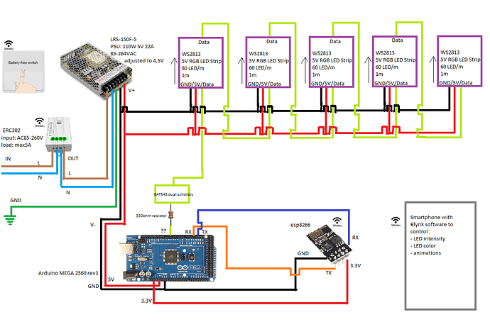
Came out with the below wiring, so that I can control my leds via my phone.
Would that work out, considering that I want to be on the safe side (i.e. as if I will have the 300 leds at full white) ?

A set of questions, hopefully that will be all and it will help others as well :
0- is the wiring correct regarding the supply points ?
1- I want to add wifi to my Arduino Mega. Is ESP8266 good ? or better go with something else (like wemos pro mini or wemons mini?) ? I need AT commands and good frequency. Any recommendation on where to buy that (Europe) ?
2- Can I wire the 3.3v pin of the Arduino directly to the ESP8266 (or alternative of point 1) or do I need a voltage divider (if so which one?)
3- do I need to add any resistor or diode or else between the Arduino and the ESP8266 ?
4- Do I need to also wire the 3.3v pin of the Arduino to another pin of the ESP8266 (like the CH_PD) ?
5- Between the Arduino and the DATA wire of the WS2813, I added a resistor like advised. How to wire the BAT54S dual schottky ? also, any non SMD alternative ?
6- the wireless receiving controller (switch) before the PSU has a max load of 5A, this is more than enough correct ? (220v, 110W, so 0.5A right ?)
7- any difference if I wire the DATA wire of the WS2813 to the PWN or Analog pins ? frequency issue to keep in mind ?
8- it looks like the WS2813 has 4 wires, GND, V, ci/di and co/do. I assume DI/DO is for DATA. And I assume CI/CO is for CLOCK ? where to wire that and for what use ?
9- Am I correctly assuming that wires between the PSU and led strip will need to support up to 18A (so 10 gauge is safe) while the wire between the PSU and the Arduino can be 20 gauge ? how about the DATA wire ? which gauge ?
10- I will use wireless switch that will control the ERC302 that will turn off/on the PSU. How can I add soft switch and avoid burning my Arduino and LEDs ?
11- if the PSU is adjusted to 4.5v, is that ok for the Arduino mega?
12- Marius : you mentioned “Data-In pin must not be on a higher or lower potential than the supply pins for example” what does it mean ?

Thank you in advance for your precious help !!!

Hi! The schematic looks so far pretty decent. The current wiring of the strip looks a bit ambiguious, but the parallel topology is correct, it should work that way. On a first look using the 3,3V outlet of the arduino as supply for the ESP is an issue as the original arduino 2560 board is allowing 50 mA current drawn on that pin whereas ESP8266 type boards draw up to about 400 mA peak when using its rf transmitter. Usage of a proper low drop out voltage regulator is needed in that case, hooked directly to the 5V supply and to feed the ESP, for example an AMS1117 3.3V. Depending on your software skills direct programming of the ESP could be an option, as it is supported by the arduino IDE as well, in that case the arduino could be omitted in your setup. Another thing: When connecting different boards the logic levels, that are the voltage ranges on the lines that are outputted for respectively detected as a low or high correctly, must be matching. ESP8266 IO pins are 5V tolerant (not the supply voltage) but it must be assured that a HIGH from the ESP is detected as a HIGH on the input of the Arduino. That must be checked for all 4 combinations input/output and high/low level on both ends of the line. I have not really time to check that for you currently, so my tip for you is: always consider the datasheet that exists for mostly all compounds on the market (if not, dont buy it).

0 - seems correct, dont mix pos and neg :wink:

1 - ESP8266 is cheap and there is support and knowledge from the community. ESP8285 or ESP32 are alternatives. I am buying my ESPs at ali express, the delivery to germany usually takes about 20 days.

2 - Nope. 3,3V out on arduino is limited to 50 mA, see above. Use a proper LDO regulator, voltage dividers are definitely not working here.

3 - The logic levels need to match, see above. If the level limits do not match a proper shifting circuit must be used between the components. google “mosfet bidirectional level shifter” for examples

4 - depends on your setup, google for some example setups for a ESP8266

5 - (+5V)–|<|–(Data)–|<|–(GND)

The 330 ohm resistor’s secondary function is to limit current if one of the schottkys get conductive in order to prevent over/undervoltage. If data line is climbing over 5,3V the left diode will start to conduct limiting the rise of voltage.

6 - yep, no problem

7 - The data out pin must be defined in FastLED. Secondary functions are irrelevant anyways, as FastLED generates the control signal in software via bit-banging

8 - AFAIR the second pair is for a redundant dataline. Both pairs are skipping every 2nd LED creating a interleaved chain. This is a feature of the WS2813 and enables strips to keep working even if a single LED went defective. But i am not sure -> consider datasheet and find an example schematic on google

9 - 10 gauge (AWG?) = 5 mm^2 -> drastic overkill :slight_smile: Use AWG 15 or 14. diameter of supply for the controllers is pretty much irrelevant, AWG24 should work as well.

10 - Implement it in software. Why should there anything burn ? (Beside overloading the strip with current, but that you already took care of by using proper supply wire)

11 - ATMega2560 datasheet says: min 1,8V supply for max 4 Mhz, min 2,7V supply for max 8 Mhz, min 4,5V supply for max 16 Mhz. Manufacturer guarantees for these values, but most time 16 Mhz is possible at less than 4,5V supply

12 - Many digital circuits are taking damage if the voltage on input pins are going below the negative supply or exceeding the positive supply voltages. The input stages are not designed for these conditions, for example internal protecting diodes could turn into short circuits then, possibly melting your circuit or something ^^. External schottkys limit the exceeding of the input voltage on data pin to about +/-0,3V which is usually tolerable.

Some more issues:

If you dont like SMD components, use THT types. LDO regulators and schottky diodes are standard components.

Most linear regulators need external capacitors for stable operation, see datasheet for example.

The length of the dataline of WS2813 and similar types must not exceed 50 cm in length for error free data transmission. The 330 ohm resitor’s main purpose is to reduce signal overshooting which is increasing with line length. If you encounter problems transmitting clean data (flickering, hanging colors, etc), I suggest another change here: Connect the arduino to the first LED. Use a twisted pair of a cat 5 ethernet cable to connect ground and data out of the arduino to ground and data in of the led strip directly. Keep the twist of the pair and dont exceed 0,5m length. Use another single wire to connect the 5V following the same path. Keep the 330 ohm resistor and the schottkys near the LED. This is adressing the issue that the WS2812 (and -13) data protocol has tight timing requirements and is affected easily by the signal degrading effects of long transmission lines.

I hope i do not frighten you with all that information, keep trusting your abilities. And dont hesitate to ask, if you got a problem :slight_smile:

@Marius_Kohsiek THANK YOU for all these information and for your precious time. Really appreciate the help. I will take a second and third read and see how to improve my wiring based on your comments, and hopefully come with a better one; but I wanted to thank you before that. Im happy to see that i “only” need to finish some fine tunning to make it good. I like the idea of using only an ESP rather than ESP+Arduino. I think the ESP32 would be a good one, I saw some guides online so I think it will work out with FastLed. I need to keep in mind the 3.3 voltage advises, the “security” points (via the diodes) and the signal overshooting issue but i think the rest is clear. Quick one, for question 10, it was because it was mentionned that LEDs are sensitive; so I was wondering how to avoid damaging them since i will use a switch, which i can turn on/off/on by mistake for example.

@Michel_G_Khoury The 330 ohm and 2 schottkys shall protect the strip in most cases. There are bad quality power supplies producing voltage overshooting when switched on, this could damage the strip. But today even cheap supplies have usually acceptable quality. I once bought some 5V 15A devices for 12€ each from china, they produce clean supply voltage. On the other hand, since then multiple time a single LED in a Lamp that was built failed. WS2812 and similar types are kind of fragile. Keep your soldering iron ready to replace one or another LED from time to time :slight_smile:

Just browsed some datasheets, FYI (prices on http://aliexpress.com):

LM3940IT-3.3 (0,38$)
1N5817 (0,68$ / 100 pieces)

Hello again @Marius_Kohsiek
I went through the points again and updated the schematics. Is it better now ?

I replaced the Arduino by an ESP32 and added a voltage regulator between the ESP32 and the PSU (for the psu i am looking at the LRS-150F-5 from MEAN WELL. It looks like a good brand and even if it is more expensive, i dont want to risk it).

1- Do I need any mosfet bidirectional level shifter after or before the voltage regulator ? do i need to add anything to the voltage regulator like capacitor/resistor ? I will use a supply buck module (see image) so I believe its “all included”, but just in case.

2- Between the DATA wire and the ESP32, I added a resistor 330ohm and two 1N5817. Is it enough ? is there any specific order for the 1N5817 ? maybe facing opposite side ? why 2 of them ? shouldnt it be on the 5v wire or on the GND wire ?

3- I tried to understand the datasheet of the WS2813 to understand the CO/CI pin; but didnt understand if I need to wire them to the CLOCK pin of the ESP32 or else ?

4- you mentionned the 1N5817, fine, but then you also mentioned the LM3940IT-3.3 ? can I ommit it considering that I will use the voltage regulator mentioned above ?

5- the distance between each led strips and between the led strips and the GND/5v will exceed 50cm for sure; probably up to 2m for the farthest stripe (max), so i will need to read about your proposed solution with cat 5 ethernet cable, but not sure about the current. Will it support it ? Also, how would that work, basically, the wires need to be twisted; but separated between each wire ? considering that DATA is in series; and GND is in parallel, it will be hard to do no ?

6- attached is an idea of the distance of the led stripes, the resistor and 2x1N5817 will be at the beginning of the first led strip, but i have 5 led strips of 1meter, one after the other (in series for the DATA wire, so how will this work considering there will be some distance between them), will this be fine or do i need to add again resistor + 2x1N5817 before each led strip ? in green the data wire, with some idea of the dimensions; in blue the led stripes of 1m each, in red and black the power and ground wires. as you can see, sometimes, between two led stripes, i will have some distance…how to deal with that? also, this considers that i will not wire the “CI/CO” pins because i am not sure how to do it (see qst3)

Again; thank you for your help !! i really feel im almost done with the planning :slight_smile:

Ok my friend, we have more information now, but some extra issues too because of that :confused: Ok, one after another…

0 - Meanwell is a good brand as far as i know.

1 - A voltage regulator does not need a level shifter. But now that you use a 3,3V controller on a 5V LED there is one needed. There is a nifty little trick to match a WS28XX type 5V LED to a 3,3V controller. Just insert a normal silicon diode for example 1N4148 into the positive supply voltage only of the FIRST LED. It lowers the supply voltage of the first LED by its 0,7V forward voltage drop. As logic levels of WS2812 depend on supply voltage, this will do the matching. See here Cheating At 5V WS2812 Control To Use 3.3V Data | Hackaday (BTW as WS28XX use constant current sources, they shouldnt get dimmer at 4,3V supply voltage)

2 - The protection circuit (that has nothing to do with the diode in nr.1) should be like in the picture below. Im am sorry, my ASCII art was not that clear, you are of course right that the diodes must be connected to the supply voltages. Place this as near to the first LED as possible.

3 - LEDs on WS2813 strips are interleaved. The output of a LED (or the controller) must be connected to the DI of the next(first) LED AND to BI of the one after it (second). Dont forget to check the crossing between the strip segments. The schema is explained here: WS2813 LED strip without controller - Electrical Engineering Stack Exchange

4 - The LM3940IT-3.3 serves the same purpose as your regulator module. The module should not need additional components, but consult its datasheet to be sure about that :slight_smile:

5 - The twisted pair is only meant for the transport of the data, not for supply voltage. Use them to connect a data out pin to a data in pin and the ground pins that are the closest to them. I dont know the actual limit of the output stage of the LED. Poor working setups are reported at signal line lengthes of 0,5m or more. One the other hand 2m could still work. In the end you have to test for yourself. There are some possibilites to circumvent the limits. First is to use differential line transceivers like this one: https://www.itead.cc/max485-module.html. Or you can use 2 or 3 single LED to “bridge the gap” limiting effective gap size to 0,5m. Or you could just rearrange your setup a little bit to reduce the gap sizes.

6 - The diodes will not be necessary in the gaps between the strip segments. The purpose of the diodes by the way is to protect the data input stage of the LED from this scenarios like this one: When power is switched off it can happen that voltage over the LEDs can drop faster than over the controller, since they have different power sources (5V directly vs the regulator, that have capacitors). In that case the data output of the controller is still at 3,3V while the supply voltage of the first LED is already near 0V. This could destroy the LEDs controller, as mentioned before. But a 330 ohm resistor, as it reduces signal degradation, can be added in each gap near the inputs. That will give you some additional centimeters before the transmission gets faulty. Comparing to the schematic in the link in #3 CI/CO should be the Data-In/Data-Out… There should be another input, which is the backup input. There should be no clock pins on a WS2813. Post a link of your datasheet to me may be…

So long, cya l8ter :slight_smile:

PS: Schematic below should work with either BAT54S or 1N5817…
missing/deleted image from Google+

@Marius_Kohsiek again thank you for your advises and links and further details that help me better understand the reasoning (so that i can apply same logic to future projects).
Got some questions before I can show a new wiring taking into account your points :

0- You said to adjust the PSU to 4.5v, this is done by using a screwdriver on the specific pin on the PSU, and looking what is output voltage; correct ? (just to be sure i got that correctly)

1- so based on the link, it is unclear to me: the 5v to the led strips comes from my ESP32 or from the PSU ? I thought it would go from the PSU directly to the led stripes, so do I still need the 1N4148 “hack” ? if so cant i put the 1N4148 between the 5v wire of PSU and 5v pin of the led strip? also, if i need this hack, do i need to add a 1N4148 before every 1m led strip or only on first first (technically, on the first led which i will cut out the first led strip) ?

2- clear

3- as i will use multiple led stripes chained, i will do as described in the link (the DI of stripes n+1 to the DO of strip n and the BI of strip n+1 to the BO of strip n. BI of strip 1 to ground).
Then the DI of strip 1 to the DATA pin of ESP ? actually to be exact to the A of the MAX485 ? see point 5 below for better view of what i think.

4- clear

5- I like this MAX485 module ! but some questions here ! should I have one only at the beginning of the first led strip, or between each led stripes? I saw that the module is as such :
VCC…5V
A…Non-inverting Receiver Input and No-ninverting Driver Output.
B…Inverting Receiver Input and Inverting Driver Output
GND…0V
R0…Receiver Output (to Rx pin of microcontroller)
RE…Receiver Output Enable (Low to enable)
DE…Driver Output Enable (high to enable)
DI…Driver Input (to Tx pin of microcontroller)
so should I do the wiring as such :
VCC of MAX485 to 5V from PSU; (or ESP?)
GND of MAX485 to GND from PSU; (or ESP?)
A of MAX485 to first DI of led strip
RE and DE of MAX485 to the DATA pin from the ESP
RO and DI and B of MAX485 to nowhere.
correct ??
moreover; connecting the MAX485 to 5v of PSU, there is no issue about different voltage/capacitor etc that u mentioned above ?

6- About the resistor before each led strip, where should it be, before VCC pin ? 330ohm value like you mentioned (how did you calculate this value) ?
what did you mean by “Comparing to the schematic in the link in #3 CI/CO should be the Data-In/Data-Out… There should be another input, which is the backup input.” ? was that in reference to “clock or no clock” question if so I got it from point 3 above, it’s a backup yes.

again thank you for your help and time !

Hi, there!

“so that i can apply same logic to future projects” thats the preferable way :slight_smile:

0 - yes, this is correct. Again a look into the datasheet is helpful: http://www.mouser.com/ds/2/260/LRS-150F-spec-806315.pdf

VOLTAGE ADJ. RANGE: 4.5 ~ 5.5V

Part SVR1 in the Schematic on Page 4 is the trimmer for voltage adjustment. This is a fragile plastic component, be careful with it. And check voltages with multimeter always when adjusting.

Will answer to the other points later, as I am short time today and tomorrow…

6 (first question) This value is based on experience, and some more sophisticated EE math, and recommended by vendors like here: https://learn.adafruit.com/adafruit-neopixel-uberguide/best-practices
The 1000uF buffer capacitor at strip is another additional good protection item… In your case place a 220uF or 330uF at each of your strip segments… Next week i have more spare time, then I can make some kicad schematics for you (good pcb design program, freeware)

Thanks for your swift answer !
I drafted this version (might need to zoom), taking all points you detailed and i think it is good, but not 2000% sure.
Not sure about the 330uF capacitor wiring (isnt it bridge the led stripes?), nor about the 1N5817 order/position/need (since there is a 1N4148 after, in opposite order, wont it create a shortcut or something?), nor about the MAX485 wiring (as mentionned above points 3 and 5).
When you have some time, let me know ! Its already crazy how much you helped me !
Thank you again !!

Nice diagram, which software did you use ? Ok the 330 ohms are placed ok, as well as the capacitors. The capacitors are meant to bridge the strip because their purpose is to support the power supply. You might use tantalum smd types as they save a lot of space and are having better electrical properties…

The diodes are not right. The schottkys must be placed between data in and +5V and between data in and GND, close to the first LED. Look again to the schematic i posted above. The 1n4148 must be put in series with the positive supply line of the first LED.

I wasnt expecting your answer that fast !

I made some edits as per your comments and added the gauge (dont know how much for the GND), see attached for the update.

When you will have some time let me know about the questions 1-3-5 above and what do you think about the diagram, any issues or points I forgot, all wires correctly done, and all protection in place etc ? :slight_smile:

I am using Fritzing for the schematics, found some nice library to fit my needs. Once all is done, I will document that somewhere so that anyone can use same stuff if they want.

About the tantalum types, noted. I will see if it would be helpful to design some PCB but thats another job for another day maybe…I will do that with soldering and no SMD for now (sadly).

Diodes are correct now, besides you exchanged the types ^^ Tantalum SMD are not that hard to solder BTW, they have pretty big leads…