I had an idea for a belt driven extruder, my theory being you would get plenty of pushing force but not mark the filament. using a 3mm HTD belt with a groove up the middle of the teeth, inside out, driven on one side and free running on the other spring pressed together. Thoughts? ideas?
1 Like
Why not drive on both sides?
Might be worth a shot.
Why not? i would suggest a making at least one of the bearing on stepper side a tensioner. but i would give it a go.
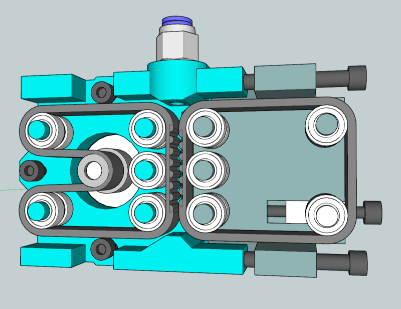
It looks like it has a tensioner on the bottom right? One on the stepper side similar for sure. I was wondering if it could be made a bit narrower since I am not sure the right side requires so much real estate. None the less, I like the idea
@Jarrid_Kerns there are 2 belts though, if you have 2 belts you need 2 tensioners.
I think that left side should be made a small as possible, and the right side should be designed to have the same belt. (save some on the bom items), i would think the belt should be a typical drive belt, (http://www.reprapdiscount.com/mechanics/53-3-gt2-belt-3-gt2-pulleys.html), this would make sourcing the pulleys easier. I also think think idler pulleys should be the the typical idler bearings used in the reprap printers.
I just looked at the price of that kit, it is too high, maybe http://e3d-online.com/RepRap-Spares-Mechanical/Bearings and http://e3d-online.com/RepRap-Spares-Mechanical/Bearings?product_id=87
@Camerin_hahn It could be tensioned with the stepper itself, by making the fixing points oval to enable the stepper to be adjusted back and forth like on the “traditional” geared extruders. That should do the tensioning just fine. It is definitely a good idea.
Yeah, I agreed on the tensioner for both sides, just didn’t word it well. Any need to allow adjustments on the filament force itself? Maybe if different materials were being used?
The screws on the right compress the filament
I wonder if the left side really needs to be like the Sells Mendel X ends. That was hell on belts and stretched them out hard. I guess if you use a belt that’s proper for small bend radii, you could be okay in the long run.
It would probably be ok with one big wheel directly driven by the motor and two little wheel to hold a second “belt” which could really be a big rubber band as long as it is periodically replaced. Whatever gets it done, man. Whatever gets it done.
The size and weight might be a problem unless you have a Bowden system. Maybe use this system to drive the filament out a flexible tube to the printer head like the Bukobot system.
I am modeling one with only one top idler (use it for tension) and the drive direct off the motor is the lower one. Other side could be driven or not.
Love it, I have a rapman with seriously bad feed mechanism design (screw onto feed stock, frequent jams)
Yes, this is something that I’ve been thinking about too!
I think you can go down to 3 bearings in a triangle on the idler and similarly on the extruder side (conditional on the belts being good and tight, I also think that the inverted tooth profile may not be necessary, the rubber belt and the amount of friction you would achieve once the idler is tightened up would be ample I suspect. I would also move the aperture the filament enters as close as possible to the belts to avoid buckling.
In saying all this, its a great design - I’d love to see a printed version :).
I am thinking that if the teeth don’t bite into the plastic, than you want surface area. Friction would be the name of this game.
I am thinking something like a flipped automotive serpentine belt would work better as you can run in one of the groves and get 4 contact points between the 2 belts vs just 2 contact points.
I am thinking squish the filament between the two belts. Isn’t that what the point was?
Why two belts why not have a soild polished surface one side, belt the other and the belt will curl around a greater surface area then 2 belts. And should need less driving force.