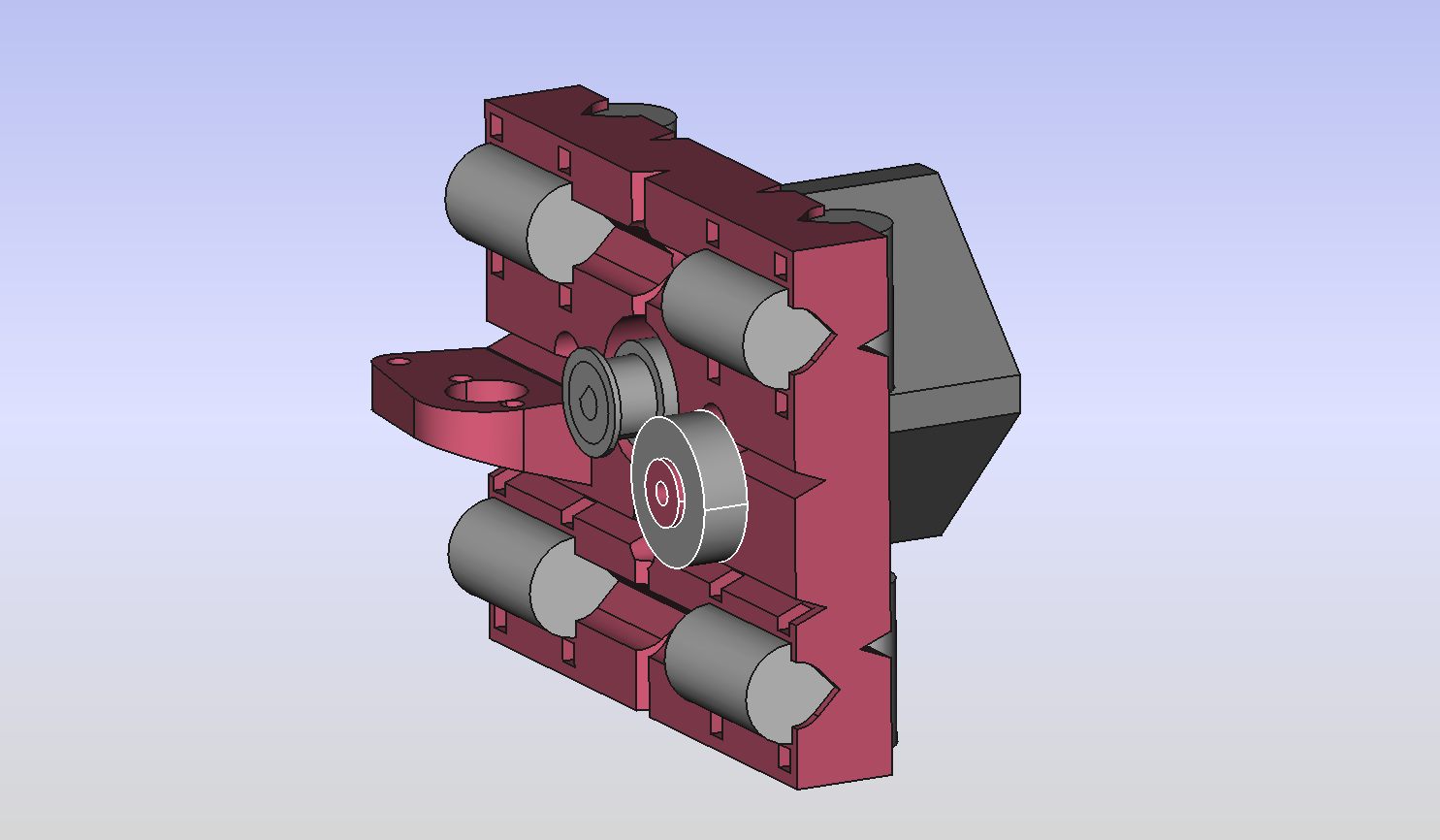
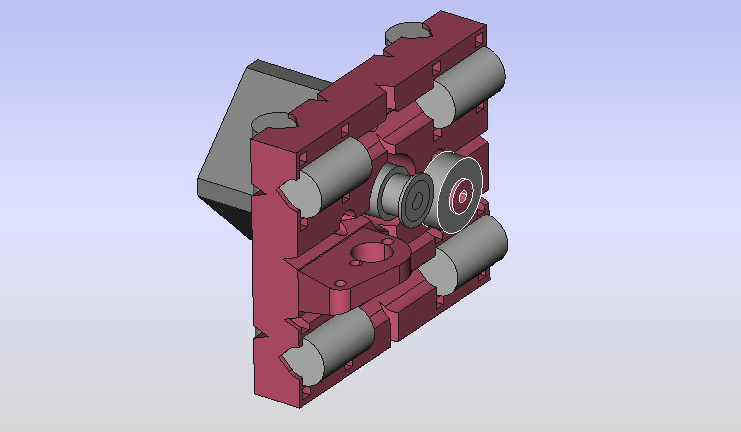
I drew this up since I’ve been waiting on some replacement parts for my #Printrbot Simple. This mod relocates the Y axis to the inside of the Z rods and spaces out the bearings, among other things. The end plates aren’t quite done yet, but I am trying to build it to support being driven with belt or wire.
Any suggestions?
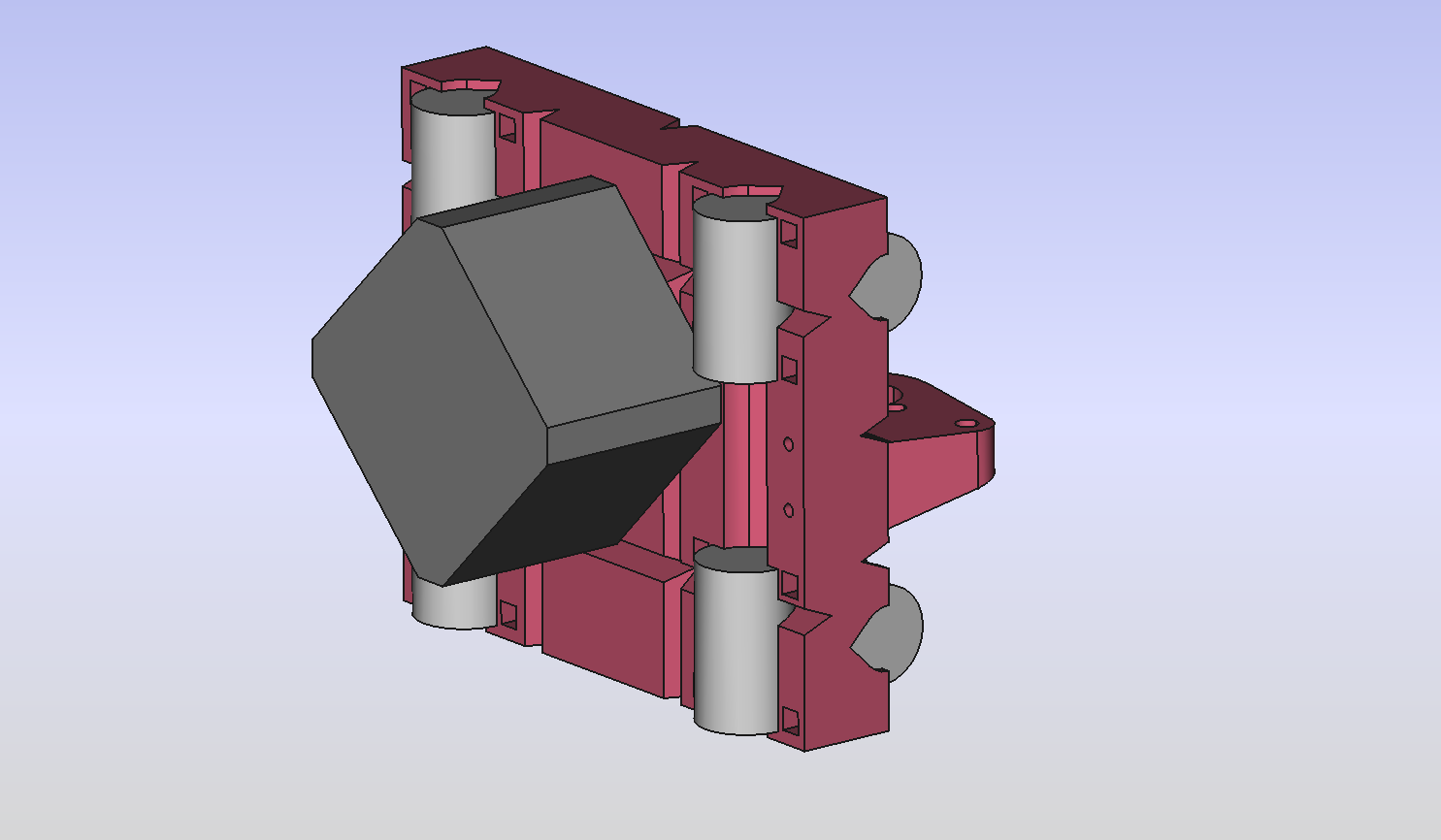
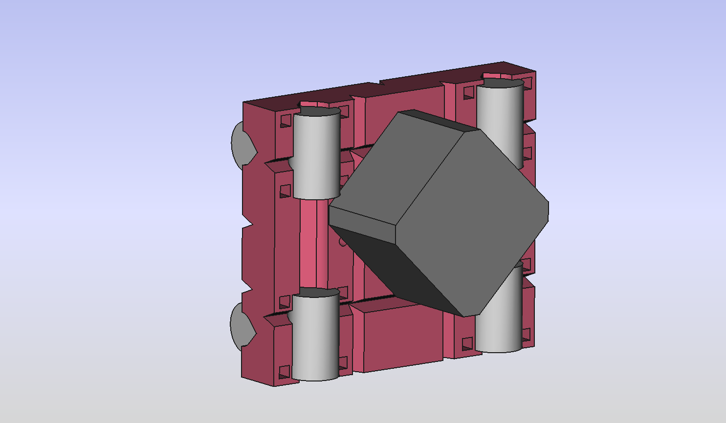
This will put all the weight outside the Printrbot base area…it may well topple the machine as the weight moves up.
The lead screw is on the other side now.
Edit: or more accurately, the motor is on the other side.
So your doing a total rebuild as where do the rods mount to the base.
If your using the current positions of the rods into the base the motor is on the outside altering the CoG.
As I don’t understand what your proposing.
This moves the y rods to be between the z screws/rods, and moves the motor to the outside of the plate. There is no relocation of the z components.
Right so all the weight of the motor now its on the outside my topple the machine when the bed is fully over to motor and the arm fully extended. That’s my only concern with this.
What is the goal with this mod? More stability? Larger build volume? Combat Y sag?
Well ok then.
It’s not clear how this would improve overall stability as you’re changing the center of gravity on a pretty thoroughly explored design. The wider stance on the Y axis bearings arguably adds stability there, but mostly only in the sense of combating Y sag (there are not a lot of forces wanting to make the heavy business end of that axis jump up).
A word of caution on widening the bearing stance: four bearings on two rods is already over constrained by one. The tendency for friction to be increased dramatically if the alignment and spacing is not perfect (nothing is ever perfect) will be amplified by the wider stance.
Z wobble can be reduced somewhat by increasing the ratio of the distance between the Z nut and the Z bearings and the distance between the Y bearings (where the load is carried) and the Z bearings. This will make disturbances created by the former have less of an impact on the latter.
It’s not clear to me that your design changes this relationship (significantly?) nor is it clear (to me at least) that putting the load bearing, um… bearings between the Z nut and the Z bearings offers another advantage.
How is this changing build volume?
This could arguably combat Y sag somewhat, but at the expense of increased friction as mentioned above. Other well proven mods for Y sag may be worth exploring.
I’d encourage you to listen to but ultimately ignore the nay sayers and introduce your own design mods regardless. There’s no better way to learn the mechanics than by changing them and seeing what happens.
I like @John_Davis 's comment above. There are a lot of questions about your design, but you should give it a try! It will only cost you a little time and filament. You can always switch to iamjonlawrence’s design (which works well for me) if yours doesn’t work out.
Let us know how it goes. I am interested. If it works, maybe I’ll switch to your design; I haven’t taken my Simple apart in a couple of months. 
Best of luck. If the group never tried new things we would all still be stuck with an inaccurate Mendel.
@John_Davis I’m not sure that you’re thinking about those constraints entirely correctly. Each set of two bearings only constrains the same degrees of freedom as one does, since they’re fixed to the body with only as much play as is needed to make sure they don’t bind — ie, they are perfectly linearly aligned (assuming straight rods). When they are not linearly aligned you’ve got bigger problems than whether the other rod causes things to bind.
Where it makes a difference is not so much when the rods are not parallel (that’s a problem with three rather than four bearings just as well), but when the body is not flat (ie, the four bearings are not on a plane). I don’t see how a wider rod distance would significantly alter that, though, not compared to making the plate out of different materials anyway.
For combatting sag, though, it’s more critical to space the bearings out on the rod than spacing the rods themselves — although you might have to space the rods on the other side out to do that.
@Jasper_Janssen I’m treating each bearing as a single point of support since in my experience they have a decent amount of play. If you put an 8mm rod in a single LM8UU bearing (the kind that pb use anyway) you can easily wiggle it by a degree or so, so I wouldn’t consider the rod properly constrained without two bearings. Since the two sets of rods are (more or less) completely fixed relative to each other, you only need one bearing on the second rod to properly constrain that axis.
Since this design is not changing the spacing on the rods, we’re just dealing with the extent to which the rods are or are not already parallel, which given that the structural elements are untreated plywood, complete parallelism is not a given by any means, depending perhaps on what season it is even. And yes, that is a much bigger problem with four bearings than with three.
I’m not all that familiar with the tried and tested Y sag fixes folks have been implementing on the pb Simple thus far, but it seems like a good idea to check those out before engaging in a significant mod that (in my opinion) only stands a good chance of addressing that same issue.
The Y sag is no longer an issue as of the late 2013 version and on. This mod should work just fine as it’s similar to Jon Lawrence’s Y extend mod. I have wanted to do the same flip, but didn’t need to when I removed the printrboard and placed it outside of the printer.
I’m not at all worried about sag since Jon Lawrence’s bearing layout is very similar and well proven. Also, I’ll be converting to a bowden setup, but if the stock extruder was used its weight wouldn’t be hanging off the side of the axis like it does now. Watching the extruder and hotend wiggle around during fast moves is one of the things that originally made me explore this idea.
If this flip does cause/amplify Z wobble, as @John_Davis suggests, I suppose I would deal with that as a separate issue. Maybe one of those printed spider couplers I’ve seen mentioned.