Hows my Wiring?

Hi all, still working on building my laser engraver.
Was hoping you guys could have a second look at my wiring, and the parts im using together.
Keep in mind, this is my first time building one, and i have little experience with electronics, i’ve been learning as i go, by reading the forums.

I also have this posted over on the Cohesion3d Forum, but the responses are a little slow (once a day) figured id see if this forum has more active users, and also get some second opinions. :slight_smile:

a forum mod over at Cohesion3d had told me that grounding the frame to the outlet was appropriate, but another user said that only the electronics should be grounded to the outlet, and the frame should be grounded straight to earth, with a heavy guage wire.
reasons being 24kV through most house wiring is a hazard, and being separate from the electronics it would help protect them.

so im looking for some clarification on what is grounded to what, regarding the outlet, earth rod, electronics, and frame.

id also like to know if i need a fuse or breaker in my machine, i figure either one might be a good idea, as i don’t have easy access to my breaker box (it’s in my downstairs neighbors apartment)

if a fuse or breaker were to be used, what kind? what size? i assume 15 amps, as thats probably the same size as the breaker for the room its being powered in.

the wiring regarding electronics that don’t have a ground to them, the C3D laserboard, fans, lights, etc. should both the hot wire, and neutral be cut at the switch? or only the hot wire?

and finally, what gauge wire should i be using? is 18AWG stranded wire for all of it too thick? do different parts, need different sizes?

I'll include some extra information about the parts used here:

Water Flow Sensor
Product Page

Switches
Product Page

  • Poles : DPST; Terminals :4 Pins;Position:2 Position(ON/OFF); ( This switch can use 12V )
  • Rated Voltage and Current : AC 125V, 16A; AC 250V, 20A

Water Temperature Probe
Product Page

  • Voltage: 5V-24V wide voltage

E-Stop Switch
Product Page
Emergency%20stop2

Emergency stop2

EMI Filter
Product Page

LPSU
Product Page

Digital Ammeter
Product Page

I can check this wiring later (no time at the moment) but here are some immediate observations.

Main switch: you should have a main AC switch and or an Emergency Stop switch and that should control the DC supplies, LPS, and any other power supplies.
AC fuse: Yes your AC input needs a fuse. You can get AC plugs with fuse sockets built in.
DC fuses: I fuse the output of all DC power circuits. Use automotive fuses.
Water flow: check that your water flow switch is sensitive enough to turn on with the pressure for whatever coolant pump you plan to use. Is that one really .6Mp = 600000P = 87 psi??
Laser current meter: consider an analog meter, it is useful to see rapid changes in laser current which a digital meter will not show (to slow).
Temperature Control: use a temperature controller that reads the temp but also has a cutout for temperatures in excess of the operating range. This will save your tube.
Interlocks Please install interlocks on the covers. You need to ensure the laser does not blind you accidentally.
Laser test switch: this fires the laser for testing assuming the “Laser Enable” switch is asserted.
Laser Enable switch: enables the LPS to be fired when the laser test switch is asserted or the controller asserts the digital control on the LPS.

If you need recommendations on parts, let me know…

Safety Grounding: The safety ground needs to have the lowest impedance possible back to the source and just because you drive a post into the earth does not ensure that. If you are in the US it’s likely that the ground pin in your house is adequate as it’s wired for that purpose. If not, your laser is not your only worry.
Make sure you have good ground connections between all the metal (covers etc) and the safety ground pin on the AC connector.
Ground your electronics to the frame at only one point. Bring all the grounds for every supply to that point do not daisy chain DC power grounds.
Use twisted-pair whenever possible for signals.
Ensure that your tubes cathode is grounded to the frame (after the meter) with a short of wire as possible preferably near or on the LPS ground.
Keep your LPS as far away from the controller as practical.
Ensure your LPS is mounted so that the case is grounded directly to the frame.

Breaker size: depends on your machine’s power budget. You want the breaker (fuse) sized to permit the normal operation of the machine and blow if it exceeds that level. So add up all the AC loads inside your machine and size a fuse for that operation.

A lot of stuff here: https://alldonsthings.blogspot.com/p/this-page.html

2 Likes

Thanks for the reply, i look forward to your next reply (when you have time)

so one switch to turn everything off/on, instead of only the individual switches i currently have? I was planning on using the E-stop switch to be the main switch, unless thats a bad idea?

does the Emergency Stop switch in its current location not work for that? are you saying that the DC items and AC items need two different E-stop switches?

I assume an in-line fuse would also do the trick?

is this a necessary thing? or an extra added safety measure?
if you have the time could you be specific about which locations on my diagram would need fuses?
I know the cohesion3D laserboard is DC powered, but it comes with its own power brick, and Cohesion3D is pretty adamant about not modifying it.

ill make sure this is working properly when i get it hooked up.
im not sure where you got the 0.6Mp from… was that on the product page?

i’ve been told this quite a bit recently to get one lol
im quite surprised that you say the analog responds faster than digital, i had someone on the other forum tell me to get an analog cause they respond slower, and therefore can see the peaks easier. as the digital responds too quickly.

This is a good idea, i probably wont get it right away, as im trying to get this machine up and running sooner rather than later, but i think this will be an upgrade ill do in the near term.
this would be considered an “interlock” would it not?

I might get some eventually, but as my current K40 clone diddn’t come with it, and i have some laser safety glasses, and its only myself using the machine. I figure its not critical at this moment.

yeah this would be handy, theres a test button on the LPSU at the moment, but having one on the control panel might be a handy upgrade.

Im not sure i understood anything of this, would this be a switch in the middle of the laser fire control wire? is this different from just turning off the LPSU? could you explain further about this, what it is, why its needed?

I was told by one person, that putting a solid 8 gauge copper line to earth, would have lower impedance than house ground, which i think is somewhere between 12-16AWG
of course the mod on the cohesion3d forum, said don’t bother, just use house safety ground.

im in Canada, but pretty sure we have nearly identical wiring standards… or close enough. lol

are you referring to how i have each ground near the switches, attached to the middle of 1 line?

ahhh, i completely forgot that was a thing, thanks or the reminder.

This one concerns me a bit, as so far no one else has mentioned this about my diagrams, and i have yet to come across this in anyone elses wiring diagrams, or posts.

is this for signal interference or something? my Cohesion3D laserboard is about 1 foot away currently. does this also apply to the seperate LCD attachment that connects to it? which is about 8 inches from it.
how critical is this?

is this your personal blog? ill check it out.

i agree with Don on the analog ammeter between tube ground and ground return. What I did was install a small digital meter on the potentiometer legs instead to show the output voltage(0-5v is 0-100%). And interlocks are a big safety upgrade, just put them in line with the water flow meter. The main Ac input ground should be tied to the frame at the grounding lug on the inside, this prevents YOU from being the grounding rod :slightly_smiling_face:

The laser tube’s return ground should only go to the ammeter then directly to the laser PSU’s return ground pin with as short a wire as feasible. The laser PSU’s ground should be tied to the frame at the lug with a direct wire(as should most grounds, or at least to a common grounding point). This doesn’t mean tie the laser tube ground directly to the frame if that was misunderstood.

Keep all signal wires away from the high voltage line to prevent interference(PWM wire to the L input, endstop wires, etc). Especially the ribbon cable for the LCD as they are generally sensitive.
A main fuse on the input line is needed, the machine usually comes with a 5A fuse I believe. This could be bumped up to 7.5A or 10A depending on the additional draw. For the DC side in-line fuses will work, the purpose is to prevent component damage/help locate problems in the event of an issue. Daisy-chaining the grounds is when you link say the controller to the laser psu, then the laser psu to the next item making the return voltage(if any) pass through every component in sequence. Thus the common grounding point.

Take all this with a grain of salt as I am no electrical engineer, just another DIYer who dows far too much reading into regulations and forums. that being said I don’t believe anything I said would cause any issues as my machine is wired as such and has never had any problems.

2 Likes

The Estop as the main switch is ok and you do not need one for both DC and AC. I actually have a main switch and an estop as I do not care for the action of the estop for normal power on-off.
Note: that Estop does not really perform a true estop function but it is the way most people use them in hobby machines. If you are interested in the Estop standard google it

An in-line fuse for the main AC power is ok. I use this https://amzn.to/39EaAFR

I recommend:

  • A main switch that powers everything on, the Estop is in this circuit.
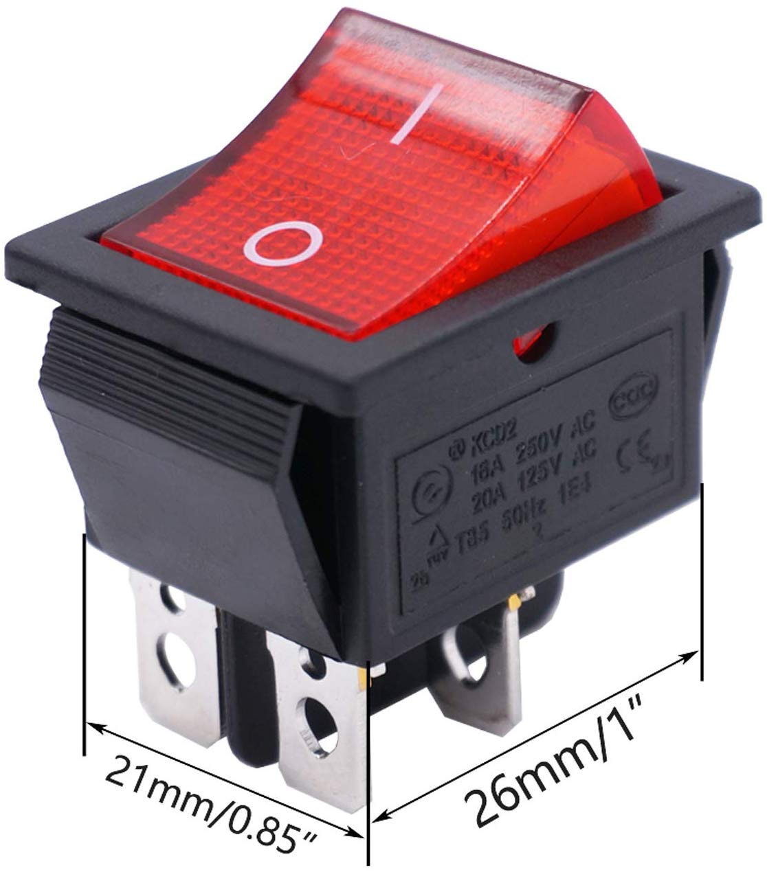
  • Additional AC switches for:
    *Accessories switch that powers lights etc
    *Evacuation fan switch
    *An air pump switch
    But: Power your AC circuits in a manner that suits how you will use the machine.

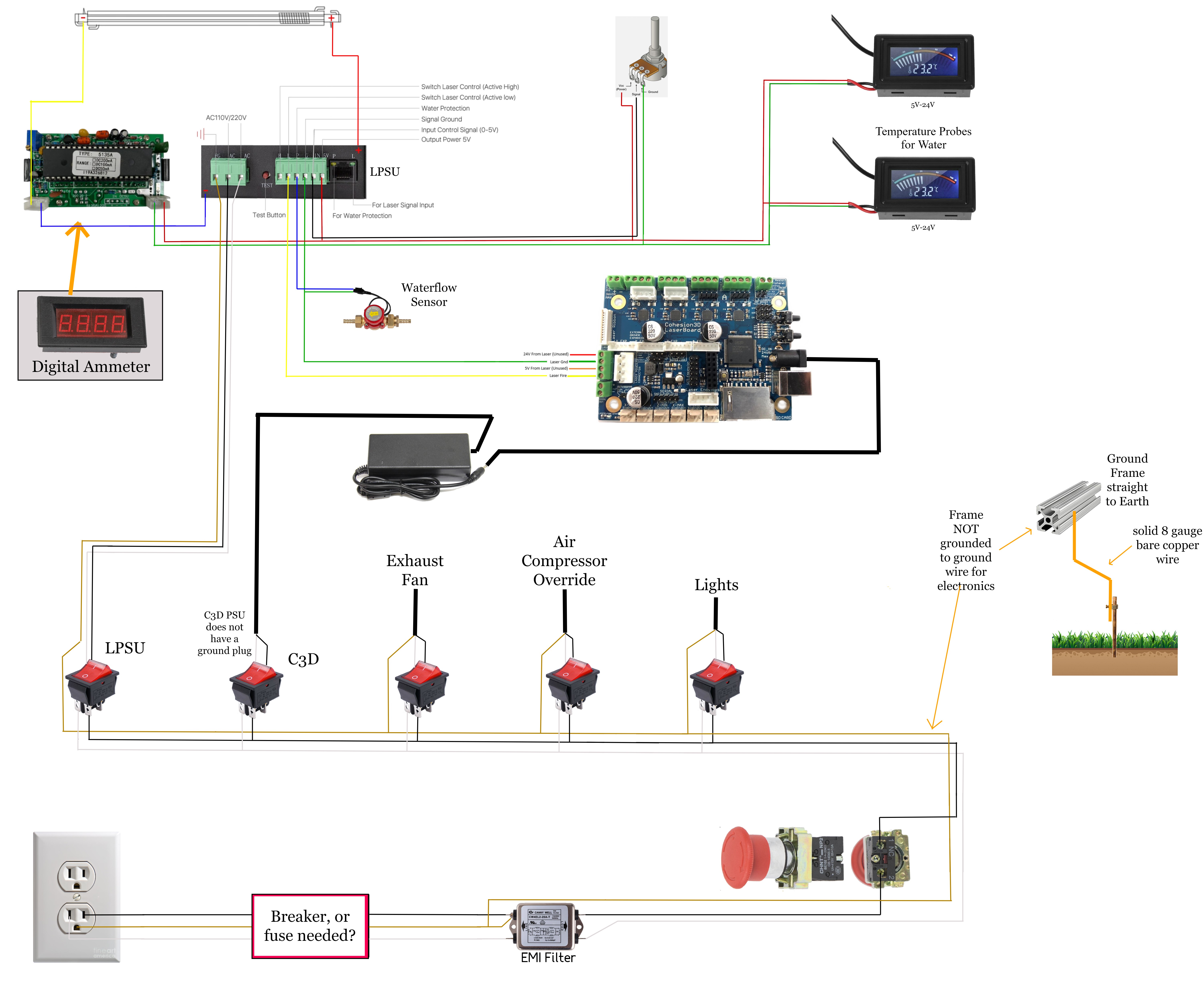
Note: I did not notice a connection to the water pump, air pump, and evacuation fan. Your water pump should be always on when the main is on the others you need to switch because for some jobs they should be off.

The DC fuses are used to protect DC devices from overload and sometimes initial wiring issues, etc; A fuse is a pretty good investment to protect an expensive controller etc.

I use a DC fuse block and separate the circuits by their load, size the fuse for each accordingly. Car blade fuses work well.
This looks like a nice choice but I have not used this particular one: https://amzn.to/2SZTRar

As a min, I would fuse something like this.

  • Fuse between the power brick and the controller
  • Fuse between DC power and accessories; cabinet light, temp controller, etc…

For the brick wiring no modifications are necessary: wire a female 2.1mm jack to the input of the fuse and plug the brick into it: https://amzn.to/37yXEPT , the output goes to the load

I found that I needed a12vdc supply as many of the inexpensive accessories use 12V. Led strips, temp controllers, etc.

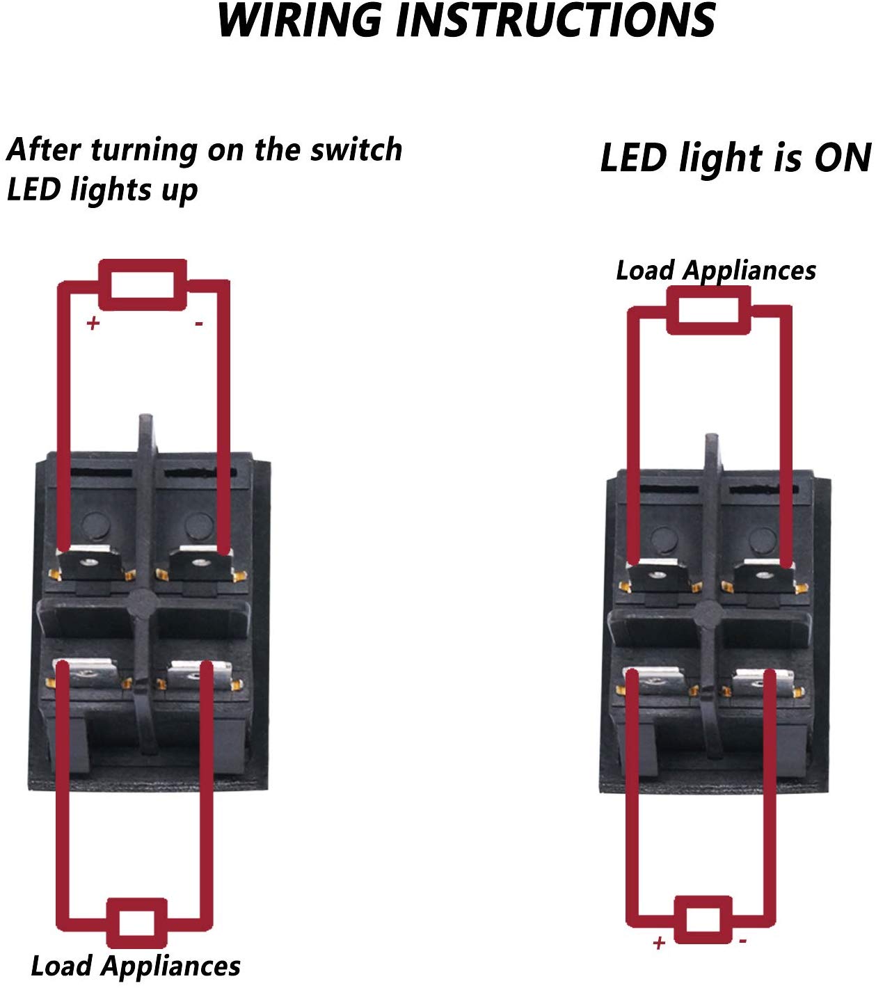
Note: Are the LED’s on your ac switches powered by AC or do they need a separate circuit to illuminate. I could not tell from the product drawing.

Note: ensure that your use of the 5V on the LPS for accessories is not exceeding its capacity. Most LPS cannot provide more than 1amp.

The water flow switch pressure spec came from the product page. I think that the unit is made for house plumbing and may not be sensitive enough. You can see some alternatives in my blog.

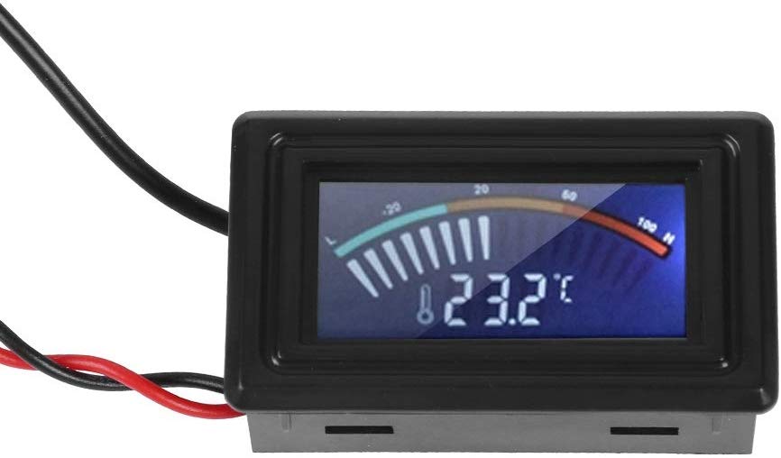
Aside from the electrical operation differences, I think the analog meter allows you to see changes easier. With a digital meter, you have to read-compute then remember each transition, some digital meters take some time to compute and display.
I do not know if there is any problem with the digital meters shunt causing a problem in series with the supply, [I do not see why it would]

Temperature controllers and interlocks are your most important elements of the safety system. The first protects your eyes the second the most expensive part of your machine, your laser tube. Yes, it is in the interlock circuit.
How does it make sense that you are interested in protecting the equipment (fuses) and not your eyes? Your eyes will be gone in milliseconds. Interlocks are easy to install and I suggest you do not wait. Users always tell me they will install temp interlocks later, then later they come back asking for advice on installing a new tube after it has been overheated.

While running a job or working around the machine, it is easy not to notice an enabled laser, and/or an over-temp coolant until it to late…

Your safety circuit has these things in series with WP:

  • INTERLOCKS
  • Water sensor
  • Laser Enable Switch

The laser enable switch is a safety feature that ensures you know, and have purposely enabled the laser. When enabled (Laser Enable Switch) the laser is HOT and two things can fire the laser, the Laser Test button and the controllers PWM signal.
You do not want the laser to inadvertently fire when you are working in and around the machine, thinking it is safe. For example; if unknowingly left enabled (by simply having the LPS on and hot) when you are working on the machine the controller could send a PWM signal and WAM your blind.
You could power the AC to the LPS up/down but it’s not best practice to cycle power supplies if not necessary. In normal schemas, the LPS is powered on but the output is disabled.
The test button on the power supply bypasses the WP circuit so it SHOULD NOT be used as a normal test fire function, its also inconvenient to get to.
The Laser Test button is used when you are aligning the optics to fire the laser and needs to be easy to get to…
There are two sources of danger to humans from a HOT laser system; the light output and the HV.

So on the panel, you have a Laser Enable [makes the laser hot] and a Laser Test that allows the manual firing.
In normal operation, you “enable the laser” and run the job.
During testing you “enable the laser” and manually fire using the “Laser Test”
I have a LED on my machine that tells me the laser is hot.

Earth grounding: how does a rod in the ground provide a lower impedance through dirt and rock back to the source than a copper wire connected from your plug to the power box… not likely.
If it makes you feel safe “drive a rod”. The important thing is that the safety ground has a low impedance to the main power box, your hot and neutral are correctly wired and all your operator access surfaces on the machine are electrically at ground. Use a ring tounge, bolt, star washer, and nut to ground tightly to the frame. The main goal is to ensure that any rouge currents flow to ground and blow the breaker and that a human is not in that circuit.

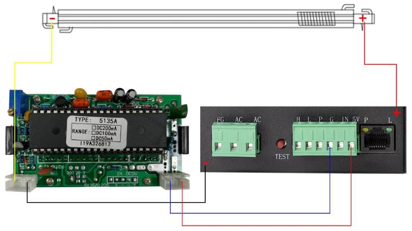
Sorry if I confused this one: The cathode of the tube is wired to the current meter who’s other side should be wired to the ground on the LPS. Ground that point and the laser power supply to the frame, keep wires including grounds as short as possible.

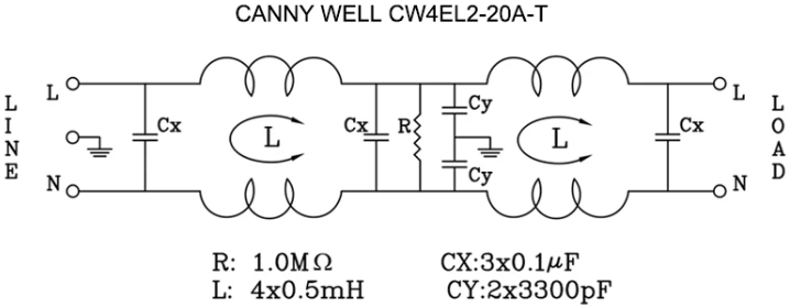
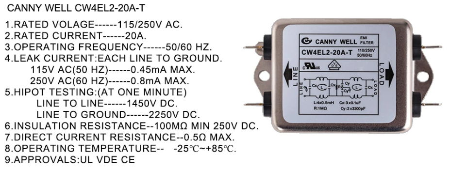
Keeping things away from the LPS is to reduce radiated noise, 1 ft should be fine. You reduce conducted noise by using proper grounding design.

Yes, that link is to my blogs…

If I missed answering a question let me know…

These machines are DANGEROUS. The LPS has a LETHAL output and the laser will blind you.
I advise you not to take short cuts thinking your will "upgrade later.

As an Amazon Associate I earn from qualifying purchases

3 Likes

I believe i have all of these in the most recent diagram (the red switches)

the water pump i did forget about, im adding it to the power line of the LPSU just after the switch, so when the LPSU is on, then so is the water pump.
the air pump, evacuation fan each have a switch of their own in the diagram (air compessor overide, exhaust fan)

im adding a fuse block, that holds 6 blade fuses, each fuse will connect just after each switch. ironically, i had purchased a very similar one to the one you linked even before i seen your comment lol

I’ll take a look into this, thats a good solution for no modification. Would a fuse be just as good, if it were before the power brick?

I believe AC, from the product page it says:
“Special attention: Light only connect to AC 110 -125V,Can light up ;Built in backlit red light (light lits when switch is in the on position).”

Then ill have to keep an eye on it and test it out, its sold by Cloudraylaser, same company i bought most of my parts from, so i hope it’ll work just fine, but we’ll see i guess.

you’re correct, ill make sure that these find their way into the machine.

i seen a youtube laser build, where the buy built a test button, with a long cable, so that he could press it from any location around his machine, might build one of these in addition to the regular pannel mounted test button, for ease of alignment.

i suppose a light up switch would be equivalent?

i have no expertise in this, im pretty clueless in this topic, so im having to rely on what different people are saying.
i think the idea, was that since both options, eventually lead to earth, the longer run of going through house wiring, plus a smaller gauge wire, would have a higher impedance than a shorter run wire, with a heavy gauge.
putting that aside, of everyone whos commented to me on grounding, only 1 person said that, and like 5 people total have said to use the outlet ground only.
so thats what ill go with :slight_smile:

so this would mean, that the main power line is grounded to the frame, and is the signal ground from the LPSU? meaning that everything is grounded to the outlet.
if this is true, then why does the LPSU have two separate grounds?
the forum mod over at Cohesion3D had told me to ONLY ground the mains ground to the frame, and not the signal ground.
or have i misunderstood what your telling me?

and thanks for your responses, i appreciate the input.