This part has shown up in a few demo’s and there have been lots of ‘why would you use that tool’ or ‘why would you design it that way when in X it’s just a single operation’, etc.
So how would you design this as a 3D model? Please list the software and general overview of the techniques used.
ex: FreeCAD: create sketch of the end, extrude, duplicate then translate. create twist using Curves workbench adding faces and adjusting smoothness.
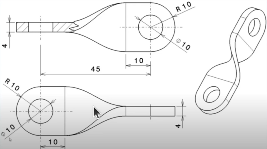
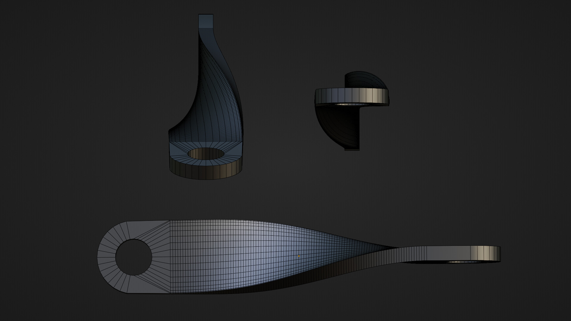
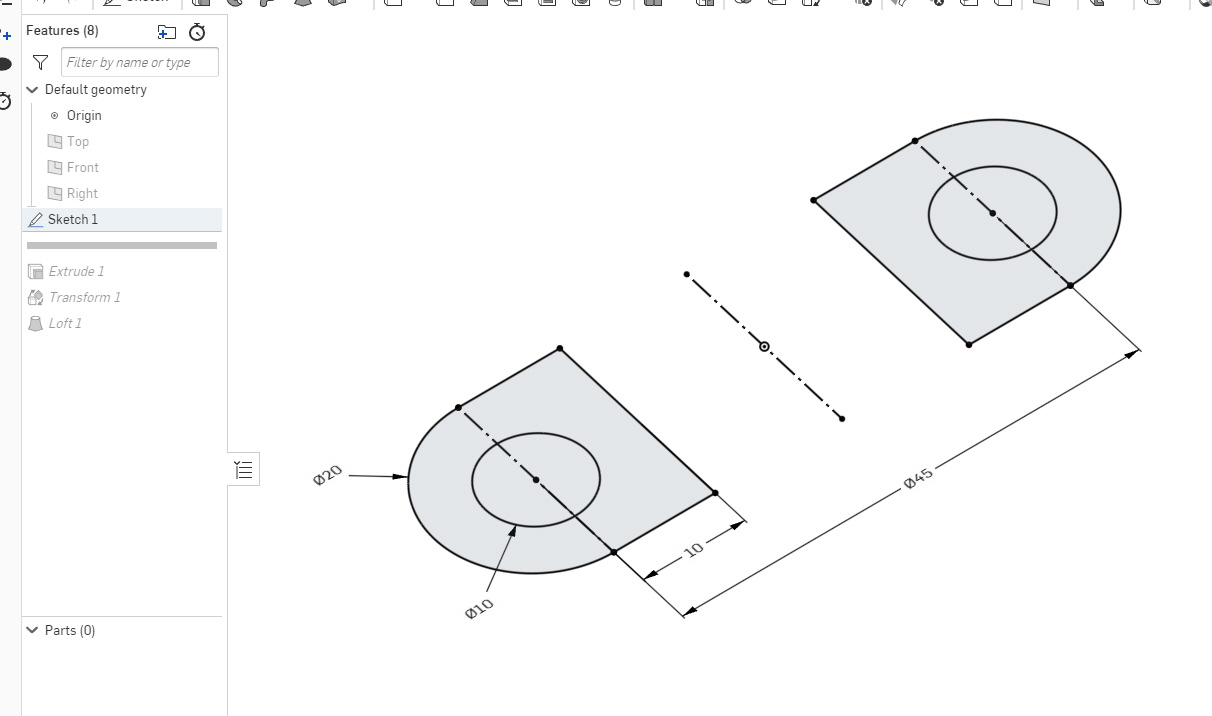
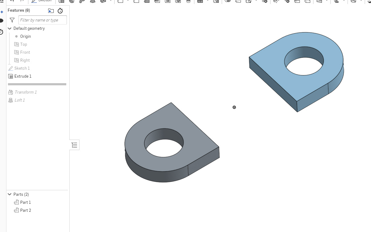
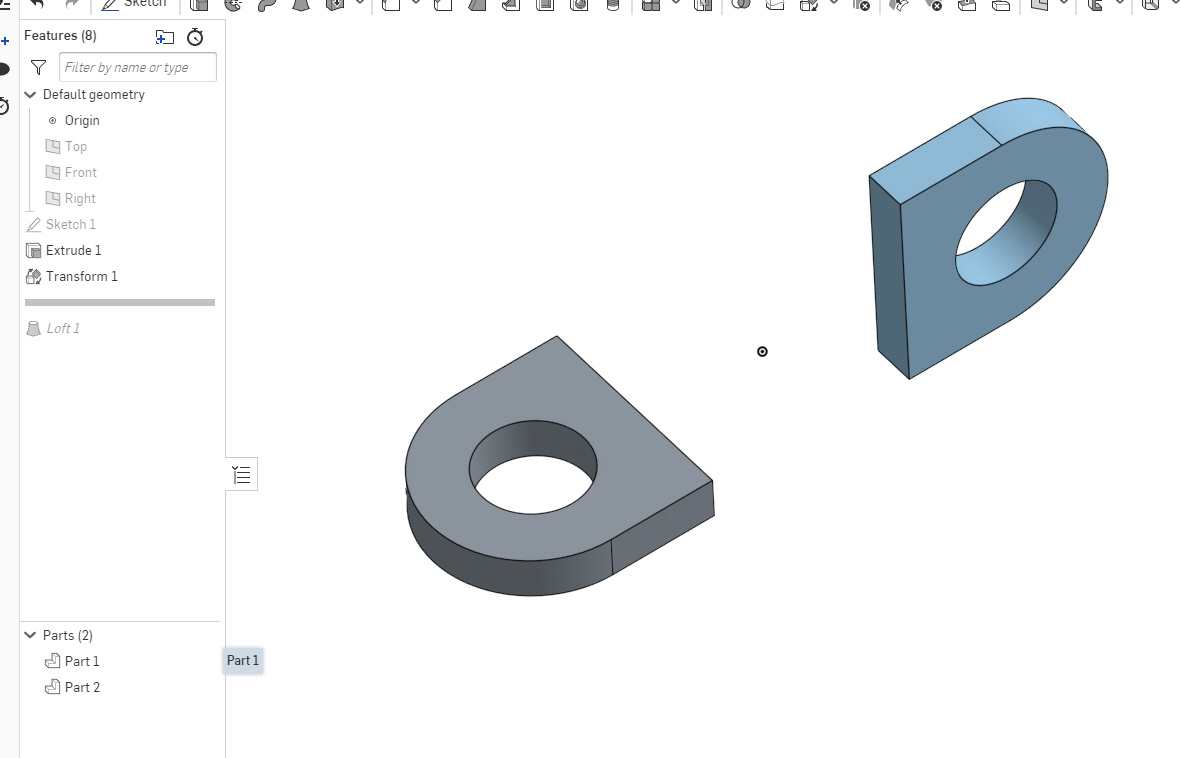
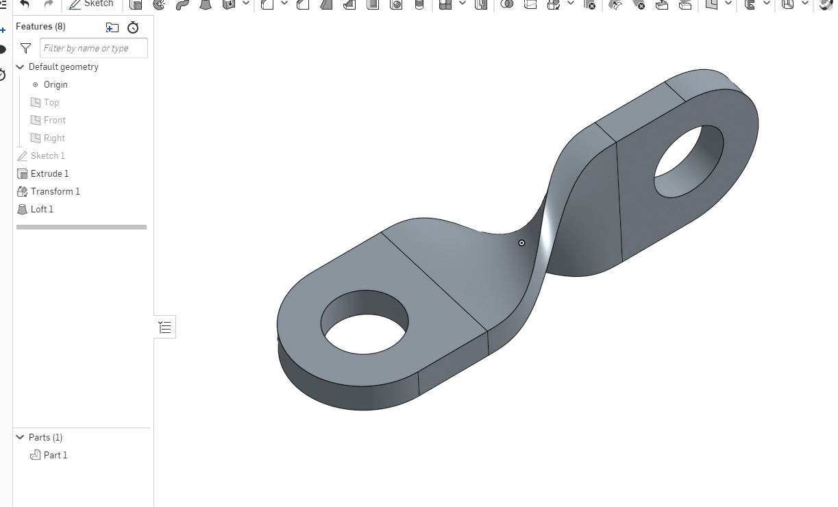
Start with the circle. Move to position. Extrude the circle to final diameter. Square off one end. Mirror and extrude to center. Extrude height. Twist on x axis 90 degrees. Different terms based on software but very similar process as mentioned.
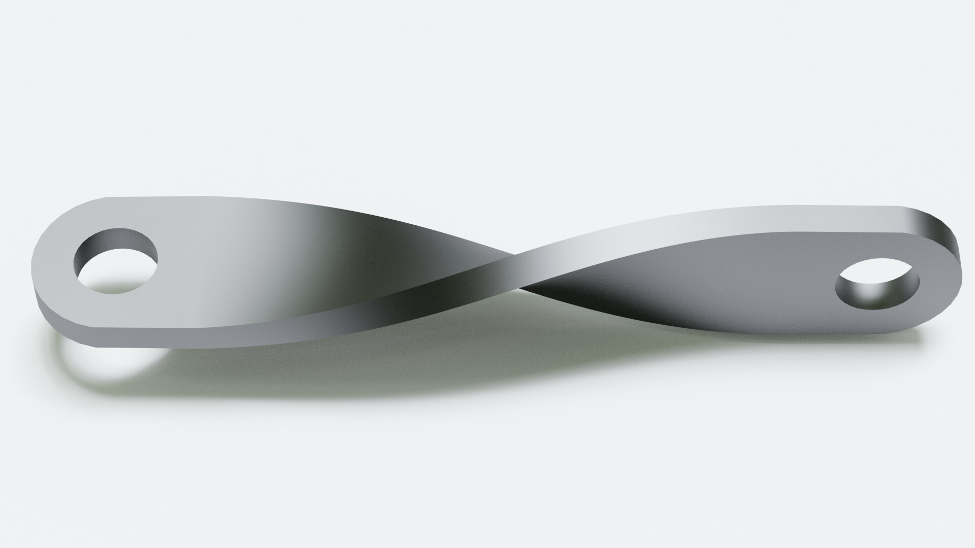
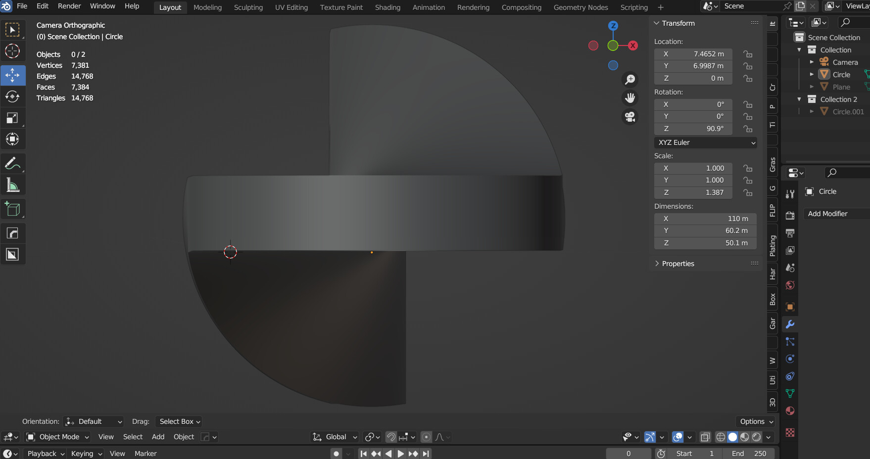
Blender 3d. If precision was need then download BlenderCam and do the same steps but parametrically.
Yes. I used the end of the bar (circle area) as the handle to start the twist for the middle of the bar.
I don’t normally model this way so I am sure there are better ways to do it. There are multiple ways to do this but this was the fast and dirty way to do it.
It would probably be more apparent if the distance between the hole centers were 45mm as there probably would be been more visual clues that the ends were still flat.
When I was seeing this done in FreeCAD and then reading the comments, my first thought was that this was likely far easier in Blender given it’s all about model building for animation which is generally far more organic in nature.
There is a video of this being done in FreeCAD and after doing it three times just to see how fast I could do it, I found the tutor forgot to select that the extrude be symmetric which added no time to the task. But it’s important to truly replicate the part from the drawing.
No wonder it looked weird to you guys. I misread the diagram.
I thought the distance from center to the middle of the bar was 45. So my bar is 90 center to center. But other than small hiccup the process is the same. It only took about 2-3 minutes to model.
Because of all the comments on HackaDay about how difficult the process was compared to what seemed like every other CAD program out there, MangoJelly Solutions did another video showing 2 more ways to do the same thing and with a bit less show-and-tell compared to the first. Just the facts mame. I still think Blender would be the quickest but since I’m a numbers guy and use parametric parameters on pretty much everything, I’ve stuck with FreeCAD as a choice but always dabble in Blender when I see something cool pop up over there.
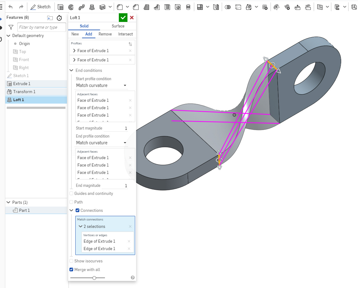
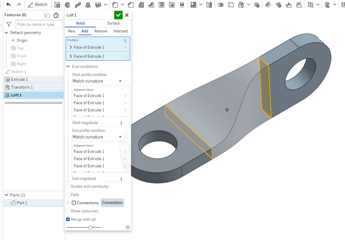
In the loft “Match curvature” (or should it be Match Tangent??) needs to be set for the start and end profile, and the one tricky bit is checking on Connections and picking two edges (or points would work too) that should connect together. This seemed to be the key that allowed it to know to “twist” the loft.