Ok, thanks a lot again, so the powering itself works.
With the correct direction i have to search again. I’m using grbl, not smoothie, and i can’t find a
option to invert the direction in grbl.
I’ll ask in the grbl board for that 
Ok, thanks a lot again, so the powering itself works.
With the correct direction i have to search again. I’m using grbl, not smoothie, and i can’t find a
option to invert the direction in grbl.
I’ll ask in the grbl board for that
I need help again with this, cant get it work.
I figured out:
– I need 0-5V with S0-S100
Sorry but that is a bit confusing for me.
J14?
Can you sketch the circuit (wiring) for each of these and identify the voltages?
Yes, i’ll make a fresh sketch.
And sorry, i mean J17 of course, not J14.
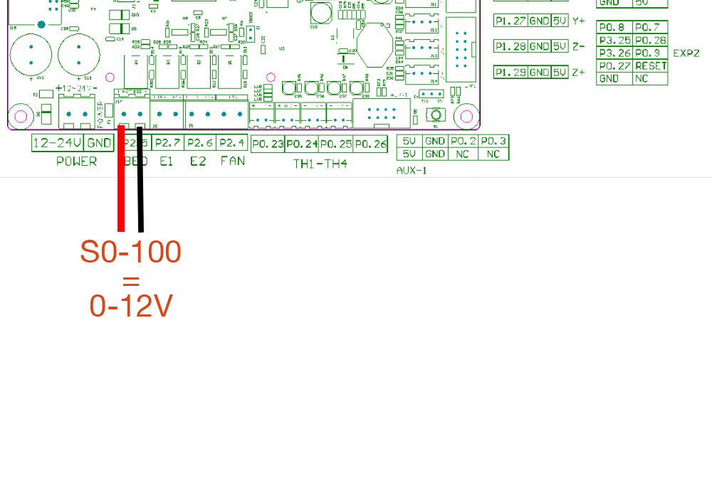
Measuring direct on J17 i get 0-12V with S0-100
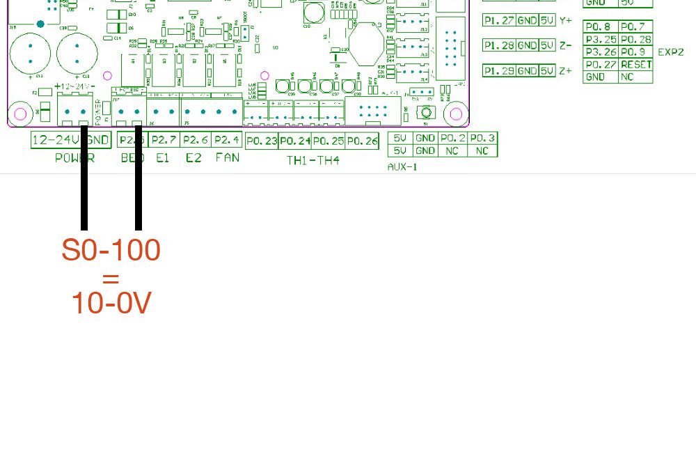
Measuring between -Power an -J17 i get 10-0V with S0-100 (wrong direction)
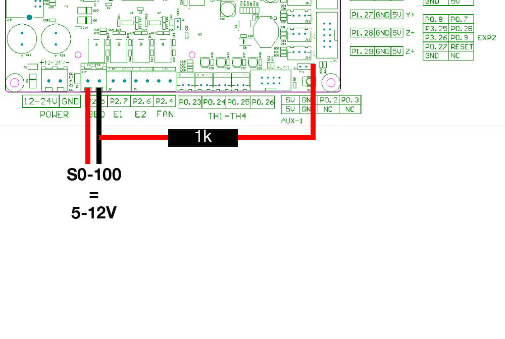
Measuring on J17 with 5V from J4 i get 5-12V with S0-100
Measuring between -Power and -J17 with +5V from J4 i get 6-0V with S0-100 (wrong direction)
That is the wiring i understand from your sketch. So i get 6-0V (wrong direction)
Ground on the Driver Board are the same at the connectors, thats not extra wired by me.
I hope now it’s understandable what i mean and whats the problem
@ManuelW
Diagram #1: measures between 12V and the PWM signal on the MOSFETS open drain. Not a relevant measure or approach especially if -Bed is not pulled up to 5V.
Diagram #2: measures between the ground and the open drain on the MOSFET. If the -BED was pulled up it should read 0-5 V. If not the MOSFET is floating and the reading is not relevant and undetermined.
Diagram #3:This is the correct circuit and measurement. I do not know where 6V is coming from, it should be 5V? Is the connection at J4 5V?
As I understand it, the circuit at diagram # 3 works it is just the wrong polarity for the diode driver. If you cannot invert the signal that is asserted at -Bed from the configuration file then you will have to add an inverter outside of the board. You cannot invert the signal by only changing how the diode driver is wired to the control board.
Were you not able to find a way to invert the pwm signal in the configuration file?
If not we need to think about adding an inverter to the circuit.
Hey Don, so my last Diagram with the complete wiring is correct?
I can’t find some possibility to invert the PWM Signal in the config 
I found a sketch how should invert a pwm signal, but cant get it work. https://github.com/gnea/grbl/issues/22#issuecomment-341931756
I connected the
The wrong direction behavior did not changed.
At a glance that looks like it should work?
Are you getting a changing voltage out just with no inversion?
OMG, i dont know what was wrong on my last try.
I did the buildup with the inverter again and oh wonder, it works
Now i get 0-4.7V in correct direction. I think the missing 0.3V does not matter?
Thanks so much Don.
EXCELLENT Work! 
Nice you found a solution!
I am the maintainer of grbl-LPC and my advise for people with TTL diode drivers would be to use a different Pin (like P1.23 on J6) and not the bed MOSFET, because the MOSFET inverts the PWM signal and grbl-LPC doesn’t have an option to invert the signal back.
There is even a precompiled version for the SBASE board whith PWM on P1.23 in the releases of my repo: https://github.com/cprezzi/grbl-LPC/releases
is the P1.23 pin a TTL or 3v level?
In my opinion P1.23 is 3V and a Levelshifter is needed, right @cprezzi ?
I have a new little Problem, but i think thats from the Laser Driver. After a while the Laser is running,
he looses Power. If a new line starts, he start burn an getting lower to off. With next new line he starts
again for a few seconds. If i power all off, wait a few minutes and start lasering again, all works as expected for a while, then this behaviour starts again. I cooled the Driver active with a fan, but nothing changes.
I think this cheap Driver is garbage, or any other ideas?
Yes, P1.23 is 3.3V but TTL high is defined as >=2.4V so it should work as long a the driver is really TTL and not analog.
About the power loss: Did you adjust the maximum current of the driver to the spec of your laser diode? If the diode gets too much current, it will overheat and degrade or get destroyed.
Thanks Claudio.
The problem are, I don’t know the specs of this diode, because I get she out of a old laser device. I only know that she have a max of 3 Watt. I’ll lower the amps and have a try again.
I assume P1.23 comes directly from the processor. Its my view that a safe practice is to buffer any outputs from the processor that need to leave the board. I would even use an optocoupler. Overkill perhaps…
Hey Guys, I found this thread after trying to get a chinese 15W PWM diode laser working on a Mks-sbase with grbl-lpc.
I want to share my solution to the inverted behaviour and logic level differences.
The Problem:
This laser has a pull up resistor on its control board. So the Laser’s disconnected PWM line measures 5v. This also means the laser is at 100% power, when disconnected - Dangerous.
When it’s connected to the Sbase, its also firing, unless it’s set to PWM 100% (M3 S1000).
The solution.
5k resistor, spare wire, side cutter.
How it works:
Typically the Mosfets complete a 12V circuit, by connecting the load(laser pwm line) to ground. PWM @ 100% = 0V.
What these steps do is pull the Load(laser pwm line) to ground with a resistor by default. PWM @ 0% = 0V.
When PWM @100%, the Mosfet “switches on”, and pulls up the PWM signal to 5V.
Might sound complex but it worked- we’re effectively swopping the side of the mosfet that we’re working with. This inverted behaviour works perfectly for my laser now.
Another thing I had to learn was that the PWM would not fire (e.g. M3 S1000), unless the machine was homed and jogged. This was frustrating to learn.
What you did is basically change the mosfet from a “pull down switch” to a “pull up switch”. This might work, but I would rather change the (cheaper) laser driver than the expensive controller board!
If you replace the pullup resistor on the laser driver input with a pulldown resistor, the laser will be off when the input is disconnected. Then add an optocuppler to the 3.3V pin P1.23 configured as a pull up switch for the laser driver.
For a laser, you should use M4 instead of M3. M4 only fires on G1-3 with power adapted to feed (accelleration/decelleration).
Exactly, a pull up switch.
I agree with you that I did some severe hacking to the control board, but it was my preference above modifying the laser! In my case I scrapped the Sbase for some reason before from a 3d printer build- so I was lucky to have it work when I tried it with the laser.
Despite this, do you think this fix could hold up?
Thanks for the advice about M4 and M3- its just a easy command I use when test firing the laser. M4 should be used when doing jobs!