Hi !
I have a two trees laser engraver with a Makerbase DLC V2.0 controller board.
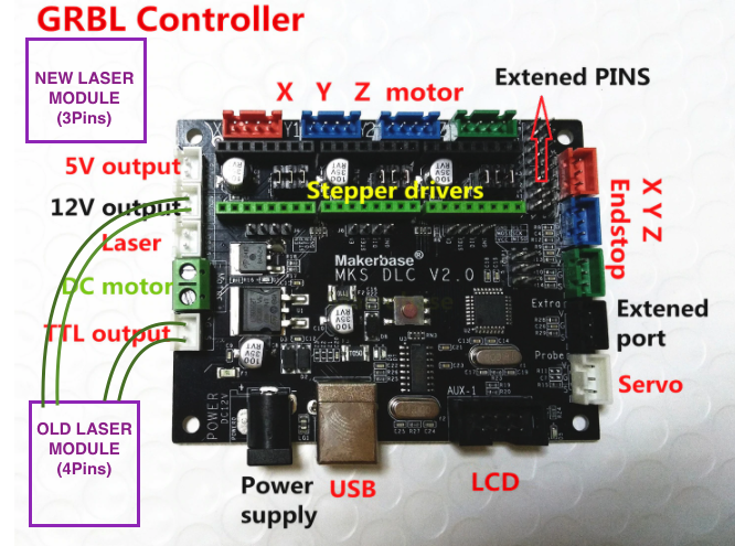
On it, the Laser got 4 pin : +12V , -12V , TTL-G , TTL-S
I want to upgrade it with a 20W laser from ORTUR with only 3Pin (I suppose +12V , -12V , and ???)
I don’t know if it’s possible.
Does anybody have an idea how I could plug it ?
Thanks
Do you have any specs on the diode drivers interface?
BTW that is not 20W laser its 20W electrical 5.5V optical.
I guess they claim to have a 7W version now…
The diode is 5.5W optical (20W is written on it but it’s the electrical power)
Thanks
Do you have any interface specs for the one you are upgrading to?
Likely the ??? is a PWM signal but the interface type would help.
My old laser module (2.5W) have 4 pins.
My new laser module (5.5W) have only 3pins.
I suppose the 3 pins of the new laser module are +12v, GROUND and PWM+
So where do I plug de PWM+ ???
Thanks for your help.
I have some problem, please help
1 Like
Please provide the model and any other information you can for the diode module you are using.
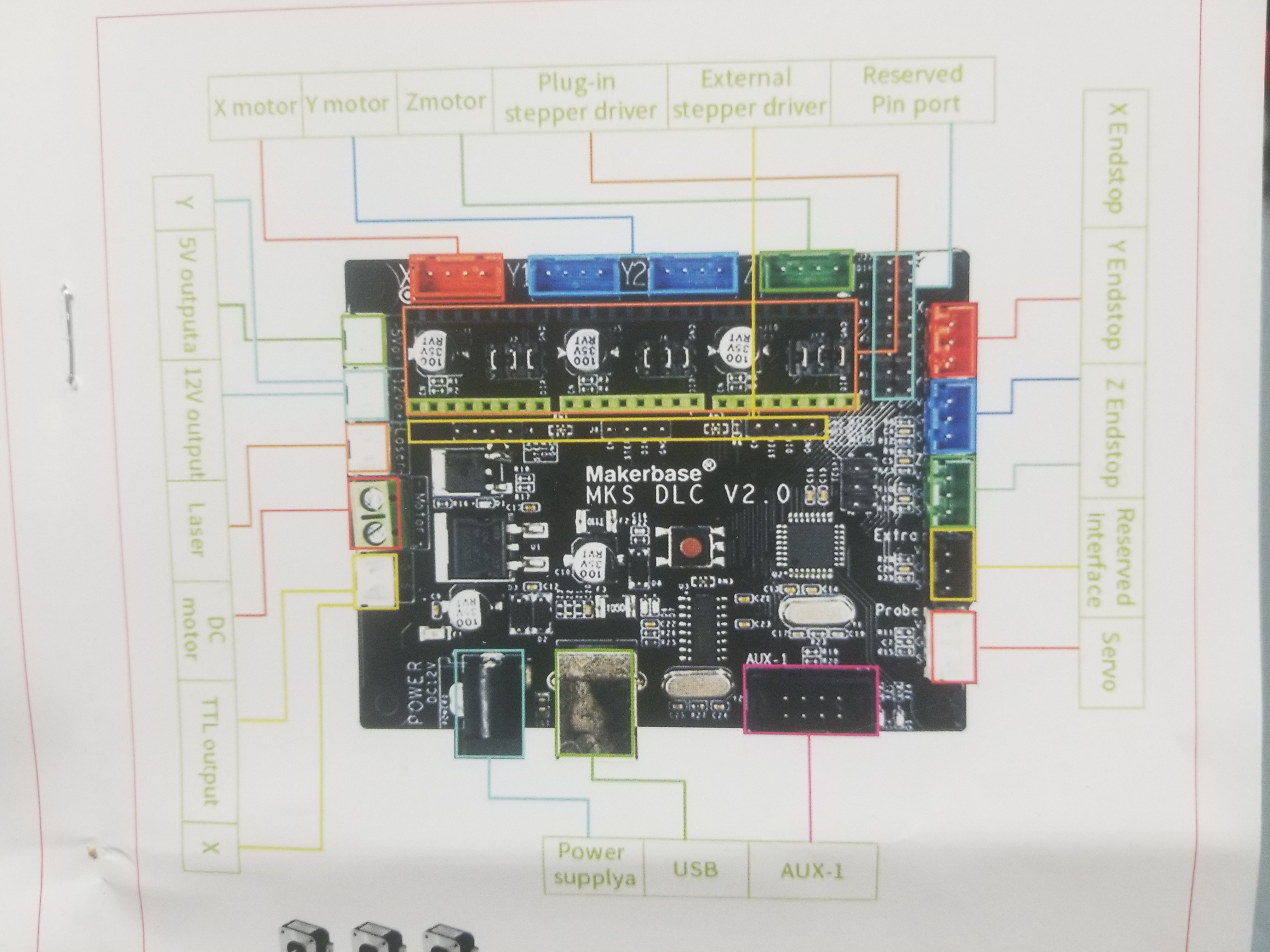
here is a picture of the card manual :
The machine is Alfawise C30
Original laser : 2,5W
New laser : 15W
link :https://fr.gearbest.com/laser-engraving-machine/pp_009955761445.html?wid=1433363
I hope it will help you
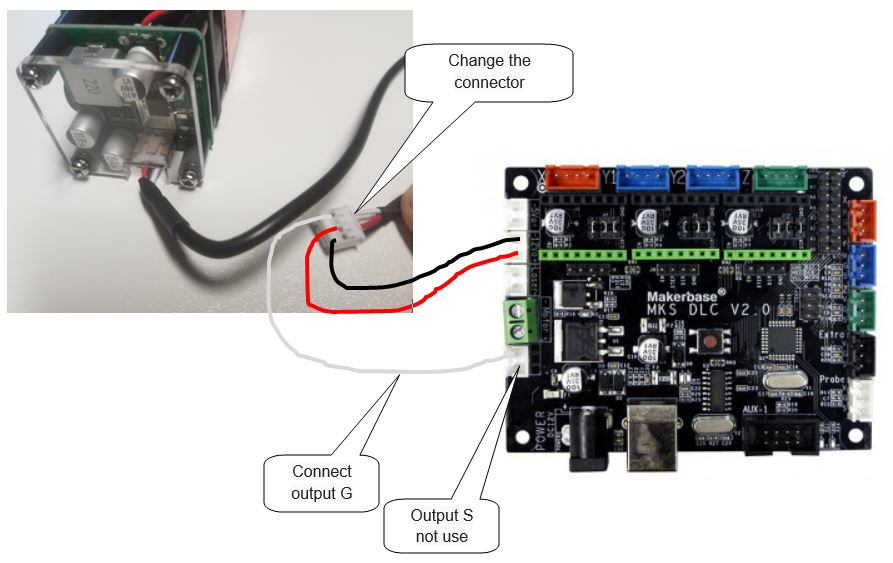
Hola, espero esto te sirva el láser 3p y su conexión a la MKS DLC V2.0. TTL-G puenteado a Tierra.
Por otro lado tengo la misma placa y quiero conectarle un láser 4p, me puedes indicar como lo conectaste?
Saludos.
2 Likes
Este es el láser 3p
1 Like
Translation:
Hello, I hope this serves you the 3p laser and its connection to the MKS DLC V2.0. TTL-G bridged to Ground
On the other hand, I have the same board and I want to connect a 4p laser to it.
Greetings.
This is the 3p laser
Thank you for your answer,
I finally changed the PCB plate to this one : https://www.amazon.fr/QPX-Triaxial-Tableau-contrôle-Contrôleur/dp/B07D211NKD
and now it works!
Thanks again and Have a good day!
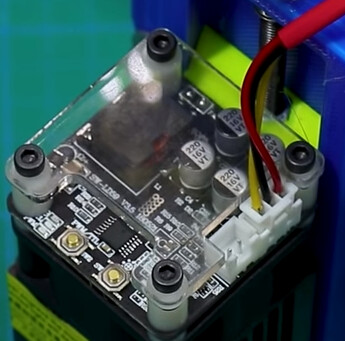
I have a 30 watt LED laser, similar to your picture. I also have a couple others that I’ve collected. All of the current lasers I’ve dealt with are simple 12 v, ground and a ttl signal, usually PWM if you want to vary the power output of the laser. I don’t know that board, but looking at this shot, I think you have the TTL control backwards. I.E. I am suspicious that G and S are acronyms for G(round) and S(ignal). I suggest you use only the 12 v connector for power and the S or signal line as the PWM or TTL control line.
You need to refer to the manufacturers documentation on input/output characteristics of all devices you wish to interconnect.
Most electrical equipment shows ‘input power’ and although relative, not a great way to measure for the user, but required when wiring something up. My 30 watt (2.5 amps ‘input’) is estimated to be a little over 7 watts output. My control board would not supply that much current via it’s 12 v connector, so I added another power supply specifically for the laser.
As a warning… I always use a voltmeter to check the ground of any Chinese power supply. It should show 0 volts or no difference in potential. One of the spindle motor power supplies I got with a motor showed 40+ volts between what we would call ‘grounds.’ Even hooking up my scopes’ ground to look at the output would have smoked something. Many times a few bucks more supports the ‘you get what you pay for’ theory.
Order a cup of coffee, relax, you’ll figure it out and it’ll come together in the end… [(8’)
4 Likes