High voltage meter

Have planned a high voltage (hv) meter addition to my laser for almost 8 months. The initial problem was procuring the resistors that I needed. The first and second orders never materialized. I needed 600 Mohms of resistance to produce a 50ua (full scale 50ua meter) deflection at 30kv.

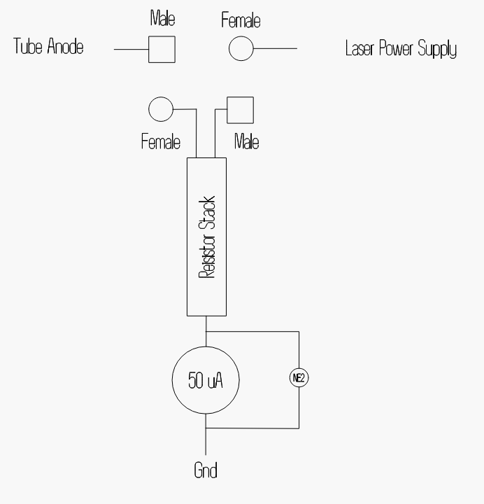
It’s quite simply a resistor and a meter to ground. There is a neon across the output to ground in case of a loose or open connection.

The hv resistors were not the issue, it was more of ‘my safety’ that was on my mind. Working with hv you learn respect for it, if you don’t start with it.

3/4" acrylic tubing, 1/8" walls gives me a 1/2" hole for the resistors to reside.

With a dielectric strength of between 17.7 - 60 kv/mm. 1/8" is 3.17 mm, conservatively 3mm x 17 kv/mm = 51 kv. About 50kv protection in a 30kv circuit.

I purchased 300 Mohm resistors.

Soldered them end to end…

Check fit tube

The resistors were then potted with epoxy resin which is known for dielectric strength, but I could not really find significant actual data. Watching a crazy guy on the internet who built some high voltage multipliers (at or near the 30kv area) just used regular hobby epoxy and has them in his hands. So I used what he used.

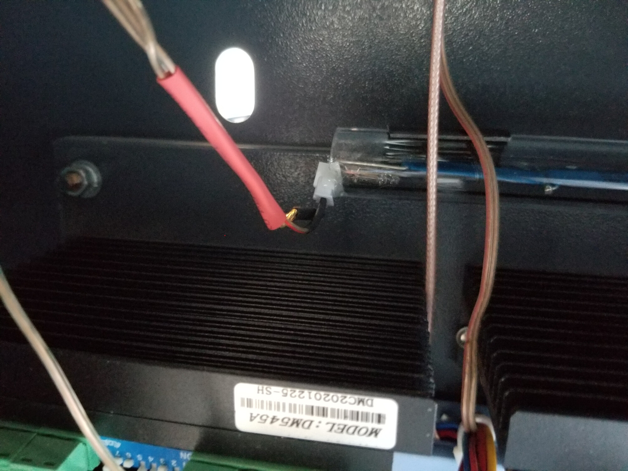
Here is the ‘hot’ end.

This is where the meter connects. The ‘top’ one in the photo is the required ground. The neon is only a safety precaution. If the load is removed (like the meter ‘opens’) you could have full hv on the meter. The reasoning is that over about 90v the neon will conduct.

I would like to mention that the identical connectors were on my 60 watt supply that I purchased from Amazon. Found out differently when I went to install. The inside male/female were of different physical sizes and would not mate. Fortunately l had purchased them as a ‘pair’ so I changed out the lps set, so I can remove the meter and reconnect the lps back to original.

I know you can’t see the difference in size, but trust me, it didn’t work… :frowning:

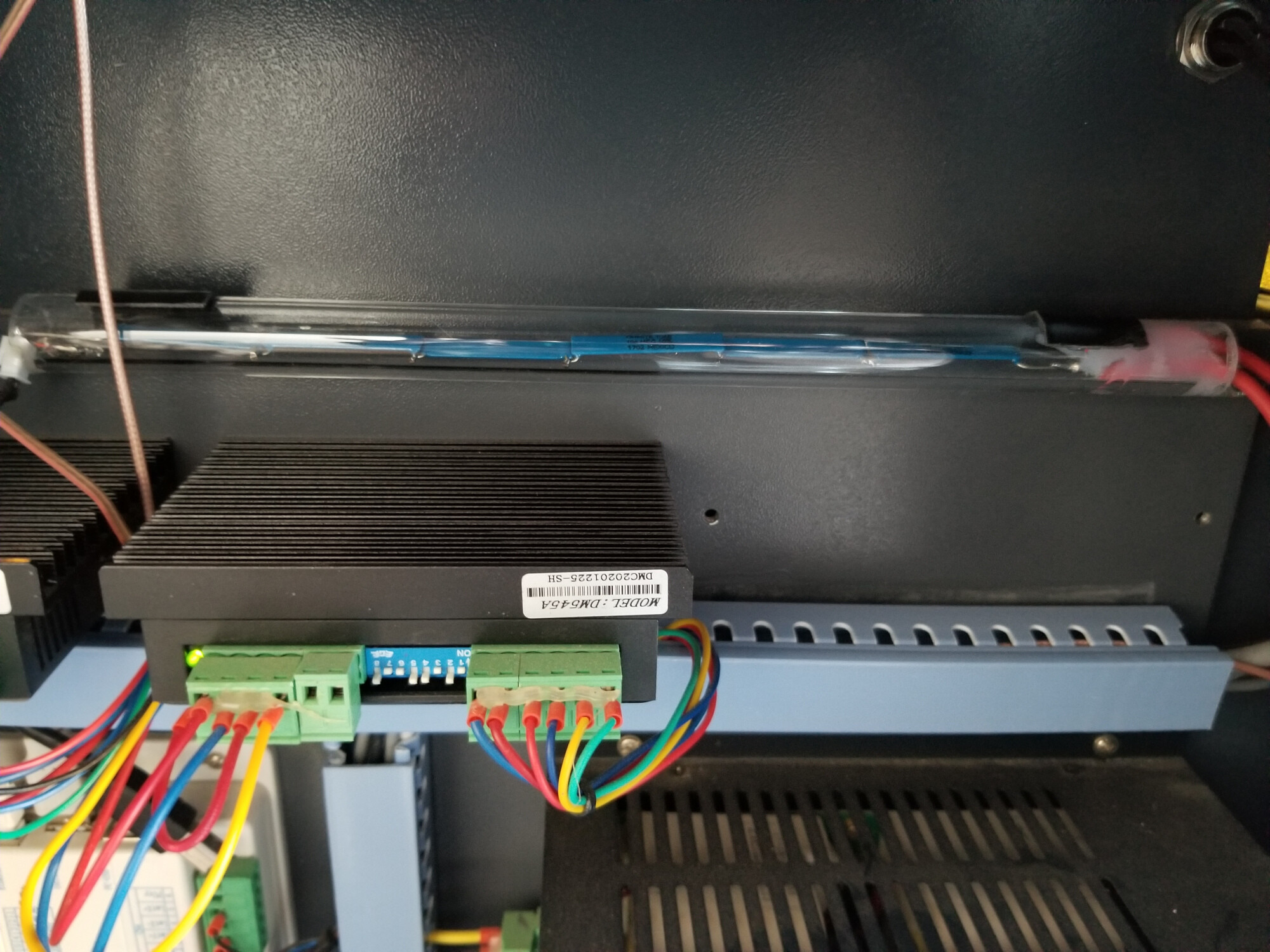
It’s ‘stuck’ in the machine with the 30lb 3m double sided tape. I will make a mount for it.

This is a video (albeit poor) shows it operating. It’s cutting out a meter drill hole template.

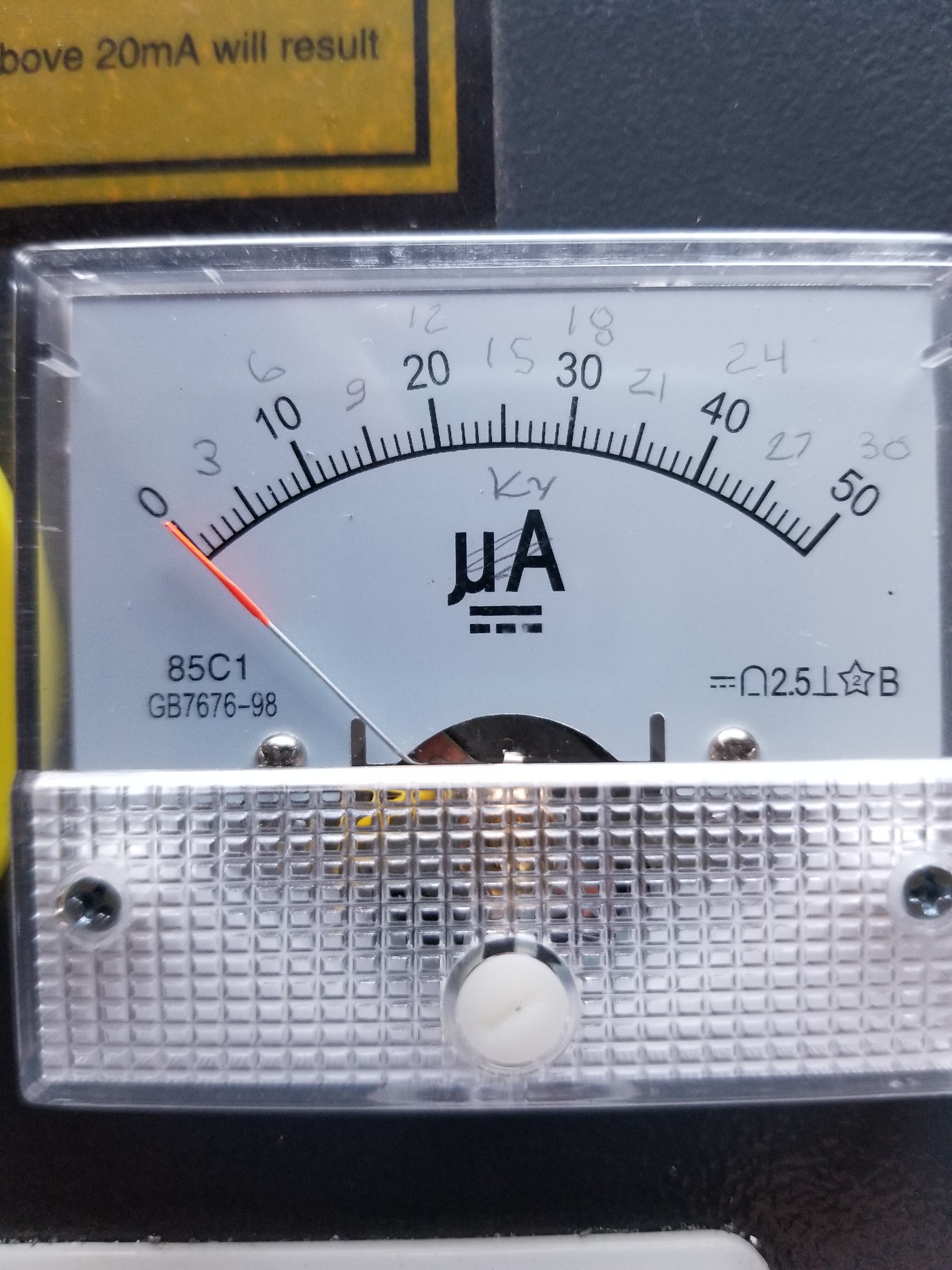
Still a working project, but there was some interest. I did have another 30ma meter I stole the face off it, but didn’t put it on this 50ua. Now that I’ve moved I can’t find it, so I have one on order. Just need to figure out how to change the lettering on the bottom from ma to kv…

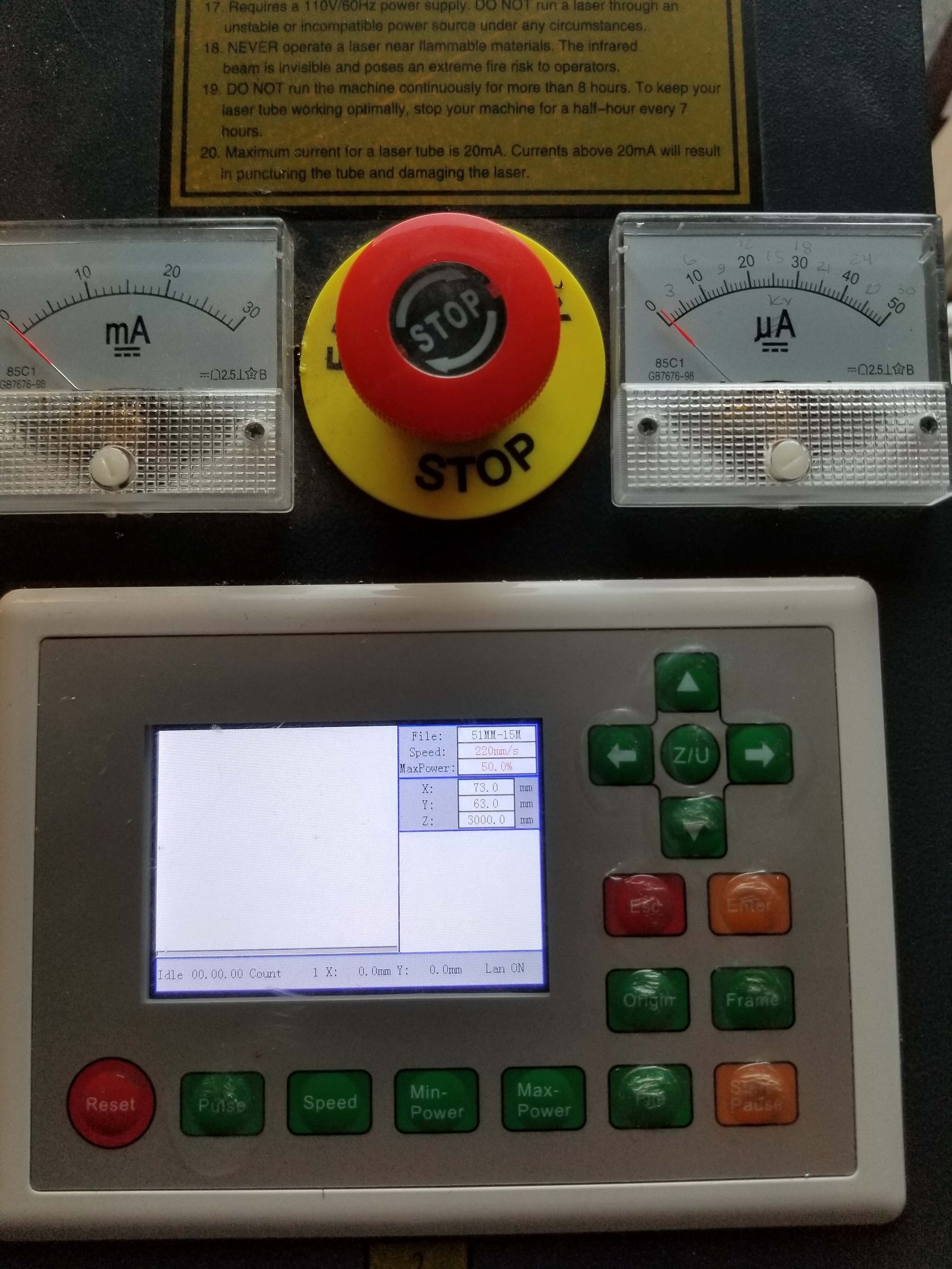
Console now looks like

Meter is marked (with pencil) so I have some idea…

Finally replaced it with a 0 - 30 kV scale face.
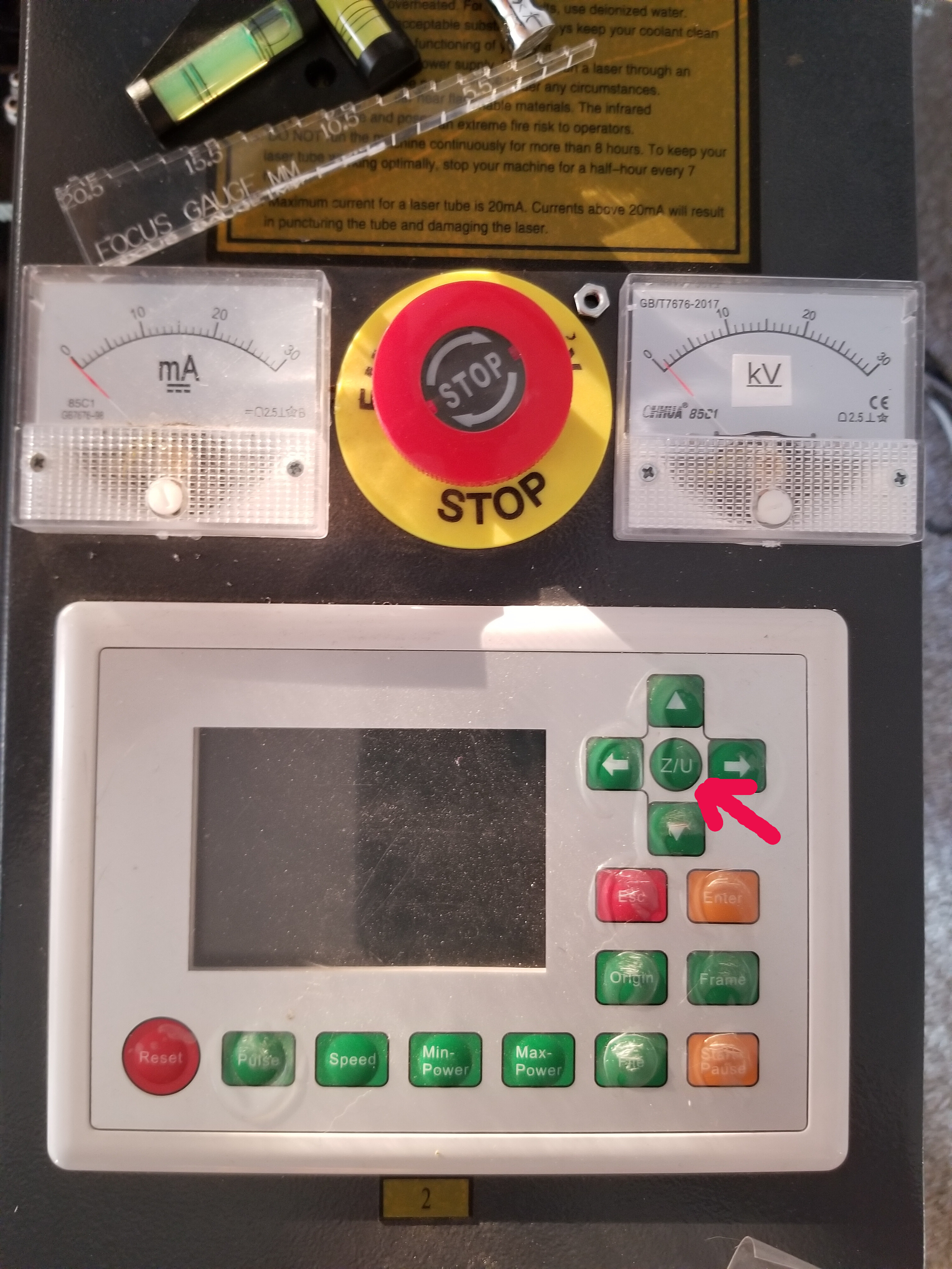
:smiley_cat:

3 Likes

Pretty cool project but wouldn’t there be a lower voltage in the LPS you could get to and measure which would represent what the high voltage was? Front end of the flyback xformer or something like that.

Probably, but it still wouldn’t tell me what’s being applied to the tube.

Hasn’t generated much interest. Thanks for checking it out.

:smiley_cat:

What does knowing the voltage on the tube get you?

I’ve seen it stated that knowing the current provides feedback with regards to the wearing of the tube.
Example, if you once cut through 3mm ply at 20mm/s 80% power with max current set to 18mA but later you see the same settings for 3mm ply not cutting and see your current has dropped below 18mA then you are experiencing tube degradation and only so much adjusting will get you back to 18mA max and eventually a full 5V on the LPS IN line won’t get you 18mA.

1 Like

What does an oil pressure gauge give you over a ‘oil light’. You can see an increase/drop before it’ a problem.

If, in your example the lps was having problems making voltage then you would also see a drop in current. Hopefully you would notice it before it became apparent and could confirm via the ma meter. The assumption the tube is bad is based on a good lps.

One of the most common questions here, tube or supply… I’m hoping this will clue me into abnormal operations.

I purchased this to learn on and it’s working quite well for that. Not to mention there seems little on hv and how to measure or apply it to the hobby world.

I’ve found when I use something I get used to the ‘indicators’ that show how the machine is running in it’s normal mode. It’s when you see changes that you can start wondering about the issue could be and not just quit.

Just another instrument that tells me how the machine is running, or at least a major part of the process.

Only time will tell how useful it really turns out to be.

:smiley_cat:

2 Likes

I think that it might be useful to tell if the LPS’s output = 0 but other than that I doubt its value.

It creeps me out that there is any kind of connection from the back of a control panel meter to the 20000V.

The tube is a negative resistance device. The important operational consideration is that the supply can reach the onset potential and then provide enough current during discharge.
A tubes health is characterized by its Volt/Ampere curve. This is why I suggest that when you get a new machine run a Current vs IN(voltage) curve. Over time you can see how that changes and determine the rate of deterioration of the tube.

Of the hundreds of these K40’s I have troubleshot,
Tube-LPS failures usually are:

  1. Tube dead: no or very low current, violent arching in the laser cabinet.
  2. LPS supply dead: no current, arching in the LPS’s HVT, hissing, erratic current
  3. 1&2

Learning is a good thing :). There is plenty of HV hobby information in the Tesla coil realm.

3 Likes

I’ve watched them on the scope, there is no way you going to get anything other than the rms value, No different than the ma meter. It gives you rms. The tube is only lasing when the pwm is high, otherwise it is off. The illusion of power control comes from pwm, the only control you really have is speed.

It might turn out to be a bust, but I’ve wondered about it since before I got the machine.

See a couple of the videos of the K40 arching from the anode to the case. I’m sure it’s not limited to them.

I ‘repaired’ a transmitter at the police station, back in the 70’s, when I was in school. Radio tech at the commercial radio shop. Mostly police types and the local CB’ers.

I watched the lighting strike the tower and have never seen one last so long.

The power supply box was full of tiny burnt metal parts and the cabinet coated with soot and metallic coat. This was a tube transmitter so it had a hefty power supply. There were not any plates of the transformer left or any other parts in the supply.

The radio worked fine when the power supply was replaced, about 70 pounds of parts. You just never know where it will go. Maybe it will just blast the neon and provide no protection at all, but I’ve seen this in production equipment, back a few decades… It’s a pretty simple electrical circuit, even with a neon failure it will have a ‘spark gap’ to discharge (I hope…)

I’ve tried to take precautions, but only time will tell.

I’ve hung my scope on the meter, but it’s such a low voltage and noisy, it’s difficult to read it on the scope. Working on that when time allows.

Any clue as to what kind of voltage they are producing when the tube fails and it arcs? Takes substantial voltage to make the distance from the anode to the case. Seems like 30kv wouldn’t make the distance.

In your number 2 scenarios where is the ‘hissing’ originating? From the lps?

I appreciate the feedback.

:smiley_cat:

IKN, but because the supply is unloaded its arc is pretty violent.

It does, in fact when they post a picture of an arc its a pretty reliable way of knowing a tube is bad.

Yes, my research revealed that the HV diodes go bad and/or the windings short and arc. Of course once this starts it all over as the wire in the HVT is very fine.

There is a lot more information about this LPS on my blog.

After a couple of years working with the LPS it became clear to me that:

  • Component failures are usually catastrophic killing most of the onboard power devices
  • Most of the circuitry sits at +600V. Dangerous to your test equipment and yourself to troubleshoot.
  • A new supply is cheaper than repair
  • The supply is intended to be a consumable. Its marginal output design and the nature of HV makes it unreliable.
  • “don’t touch this”

The K40 has two dangerous subsystems; the LPS and the laser. This danger is exacerbated by the silent nature of their operation. When operating normally they quietly do their thing not garnering caution from the unsuspecting user that gets their hands or face into the wrong place.

An interesting place to put a scope is across the ma meter as it shows the tube current. I never spent much time trying to make sense of this waveform as it needs a useful sync from the driving program.

2 Likes

Trying to hit the sack, but I keep forgetting to ask you

Have you’ve ever seen one with the cathode disconnected?

That would happen if the ma meter opened up.

Wouldn’t that ‘emulate’ a bad tube also? Back to the unloaded lps?

Understand about the fine wire.

Built a Tesla coil in the 5th grade with a ‘used’ commercial AM transmitter tube for the oscillator. Had to build the 800 volt plate power supply for it.

My dad helped me wind the secondary coil by making a jig for it to rotate. It was almost 3’ long, lots of winding.

I have a plugged connection wire to the PWM output, just for the scope trigger… :slight_smile:

Thanks for your time… Take care

:smiley_cat:

1 Like

I do not recall one with missing ground per se but this is one thing I have them check when I see no current in the meter.
Yes I would expect it to act as an unloaded or dead tube but moving the ground wire to the cathode side of the meter is an easy way to verify that its grounded through the meter.


I always wanted to design a repeating test pattern of vertical bars and sync on a known point in that pattern to watch the tube current across a single horizontal scan. I theorized (and the math suggested) that a CO2 tube cannot switch at the speeds we are expecting. Seeing the current clearly would prove/disprove that.


Be careful when reminiscing about building a tesla coil as a kid. It’s like comparing a garter snake to a black mamba, after all they are both snakes. This supply has a silent energy like no other I have seen in a hobby environment. Its current capability is in excess of 30 ma. I know this because I measured it. Its current while sustaining a 2 inch arc easily pegged my meter.


I built a HV lab to test these things that had all the safety precautions and after multiple surprise arcs (no shock) I decided it was just to dangerous to mess around with. I knew that sooner or later I would get lazy and then I would hurt myself.

1 Like

I hate to admit it, but I’ve been tagged with 15kv at over 100ma capable. The worst was really when I got across 440 from a faulty ground connection. Could not let go. Another engineer kicked the connector out of my hands.

Thanks for your time, hopefully you won’t read my obituary… although I know of no one that has actually expired from getting across one of these.

Many deaths from just the mains…

:smiley_cat:

My dad started a company doing this commercially in 1960.
You only need a former for the epoxy
He did, however, mix and pour the epoxy under high vacuum to get rid of the air bubbles, or better still stop them from forming in the firt place.
You may also add ‘fins’ to the design to increase the creepage distance along the surface of the epoxy.
Have a look at the insulators on high voltage power lines to get an idea of what you need.

btw he used standard, commercial 4M7 Ohm 1/2 watt resistors in series 1-10cents each :slight_smile: at your local store

I did put the epoxy in a mason jar and draw it to 23" of mercury vacuum for about 20 minutes before pouring it into the acrylic tube. It had a ‘head’ like a beer from the small bubbles. I did it with a brake bleeder vacuum pump, so I was pumping down a small mason jar… took lots of strokes… :tired_face: If I did this much, I’d buy a vacuum pump.

Didn’t have anything large enough to hold the finished tube and draw a vacuum as it set up.

I was always exposed to the vacuum strategy, but saw many people using pressure pots. Instead of the vacuum they put it under pressure to make the bubbles virtually invisible. Found a bunch of videos about both techniques. I think the vacuum is much safer if you have a failure in the system somewhere.

I had limited room in the machine so had to limit my size. I looked at using many smaller resistors, but the overhead of just wiring them together appeared tedious. Have to make sure they are far enough apart to ensure some limit of safety.

The original was built with 1% resistors and after three months of waiting they advised they couldn’t be shipped, although the site stated they were ‘in stock’. Ended up with 20%, but it’s still relative.

I would like to be able to tap off to get about 30v = 30kv, to be much more usable on the scope. I’d like to get a good handle on the response time of the lps. That’s seems to be kind of a nebulous area… If I can see it on the scope, that will answer many questions for me.

Still trying to get through @donkjr information on lps and his experimentation with them. He did ask a very good question about how it knows when to limit current via the sense circuit. My supply may be different. I had to turn mine down and I didn’t see anything that would control that. There are also a couple of signals, that I’m not sure I followed.

Thanks for the comment. Take care.

Have any pictures of your dads work you could post?

:smiley_cat:

What I was trying to find out in terms of tube response was it OPTICAL response which is mostly what we care about.
I looked at various optical sensors but the tube’s power would burn up or saturate them. I looked at infrared/thermal devices like reversed Peltier devices and they were too slow. There is lab equipment that could measure the optical output but that was well beyond my hobby budget.

So I fell back to thinking that laser current somehow could be a facsimile for the optical response. Although I started to scope the current I never got to anything definitive.

My unproven intuition tells me the response of this tube is much longer than you would need for the speeds of a K40, but then again a K40 works!. The most useful thing that came out of the research was a ballpark setting for the PWM frequency.

The fact that k40’s worked and the scary nature of the LPS caused me to stop further work. Even if I was right about the actual optical response it would be of academic value at best. I moved my focus to understand the LPS design so that I could help users troubleshoot HV problems.

BTW you can measure the HV with a meter or a scope using an HV probe. A purchased version of what you built.

… connected to a DVM or scope. Test it carefully before you hook it up so you do not fry something.

Even though the voltage rating on these was less than I wanted, I bought these to help eliminate stupid accidents.


Keep in mind that the tube is a negative resistance device, essentially a high energy threshold device. Correspondingly the voltage behavior is complex. I concluded that even if captured it would not provide much information on the resulting optical response time.

Noone seemed to have captured the optical output of an electronically pulsed CO2 laser and related the discharge to the tube’s optical waveform. This may be because CO2 lasers were designed for continuous operation. Pulse operation was achieved by optical switching devices at the output vs controlling the tube’s power.

Sarbarmultimedia had one session where he did look at the output with a scope and it was quite interesting, again it did not tell us anything about the optical response but it did show response times that were closer (ms) to what I imagined.

2 Likes

Watched Russ’s trip to Florida a few times. Very interesting, as you pointed out and not sure I really follow all of it 100%. Thanks for posting the link, I hope others take the time to watch it.

My probe for my VTVM/osilloscope disappeared a years ago. I looked into this, but I’d have to break the insulating barrier to really go to the line. I’d prefer not too.

The optical angle, I didn’t consider. :frowning: I understand about the optical sensor problem, slow vs expensive. I quit looking for anything like a luminous meter sensor for these in IR.

What kind of price range did you finally quit looking?

It would be much more informative if the graph information could be done sensing the optical output characteristics as it goes through the cycle. A time line would have been of assistance.

I can set my Ruida (1kh pwm frequency) to 250mm/s and burn a 50% line. It burns a clean line, as expected. If I up the speed to 1000mm/s I can see the individual pwm pulses in the material. 50% pattern of on and off. It was pretty evident that my view of the being able to control the lasers power was an illusion. Even though I knew it deep down, kind of drives it home.

The performance is there. Most of these supplies are rated at a response time of <= .1ms (I think, that’s 90% power), but I’d like to have more information. I’d like to be able to relate the stuff…

You mentioned the ballpark settings for the pwm, what/how did you come up with them? What did you find.?

Thanks… Need to run, it’s honey dew time…

:smiley_cat:

2 Likes
2 Likes

A brilliantly simple way to get an idea of the degradation of a laser that probably sees a bit more use than most. So when it gets a bit closer to it’s end of life usefulness for cutting or engraving,you’ll be able to get a backup laser & support boards if you want to, well before it could cause any interruption of your workflow. I like the way you’re thinking here! :slightly_smiling_face:

I’m hoping it will be of use. Thanks for the kind words…

Take care.

:smiley_cat:

Had the resistor stack fail… I have no way to measure the resistance that hight and the meter was working… so…

I built a new one with 6 x 100mOhm high voltage film resistors. These are physically ‘flat’.

A few basic changes.

  1. I put a connector on the end of the resistor stack, the nuts on the threaded shaft were a pain to deal with in a cabinet. Epoxy connector to notch in tube.
  2. I did not ‘encapsulate’ the entire resistor stack in expoxy. I think expansion/contraction were why the original failed. But I have no proof, just the ‘feeling’…
  3. Hot end was filled with hv silicone for hv isolation near the hot end.

Full view

Hot end

Cold end

It’s been up and going for a few months… Just didn’t update the thread.

:smiley_cat:

2 Likes