My guess is that you have PWM settings incorrect. As a result, you are firing at 100% power (or more) and you are going very slow. I’m guessing that your meter is spiking over 16ma and not the 2ma to 5ma you should be seeing.
On some K40, the speed was labeled mm/sec, but was actually cm/sec. So 30 on the old software is equal to 300 on LW. As suggested, try 200 just to see what you get.
Well, you were the one that said you tested 5-20% and got those original results I would say that 10% bouncing up to 5ma is a problem. IMO, 100% is around 20ma on a K40. Of course, I only have experience with mine.
I think you are not getting the variance in Power you should. Likely caused by PWM Settings in GRBL. Look at PWM Frequency.
Also, I don’t understand the 133mm/sec limit? Where is that coming from?
I just tried again changing max speed/accel and I can’t get past 150mm/s. I’m using DRV8825 so I gave the steppers more current but still can’t pass 150mm/s.
Right now I have max speed: 8000 / accel: 2000
that gives me 133mm/s max speed.
I did change the TCCRB_REGISTER to disable the prescaler. What are you using?
BTW, I’m using the IN not the L signal so theoretically the PMW frequency is not at play cos IN is analog - it will only take the voltage into account (from the POT for instance). Well, that’s my understanding.
I haven’t tried Grbl on laser yet. I had smoothie running pretty well and then started to look at switching to Grbl due to raster issues I couldn’t solve. Then I had a forced break from laser project due to workload. I can’t really help with the settings. It’s very possible that Arduino is not able to process the steps at those speeds. The 8825 drivers can definitely do faster speeds. I run those on my CNCs and I think that’s what’s on the MKS boards.
@cprezzi does grbl have a setting for pwm period? I had this result when set to 20 instead of around 200 in smoothie but I am unfamiliar with grbl firmware
I’ve played with, compiled a few times with different options but no real change. I’m guessing that’s because I’m applying PWM to the IN instead of L on the LPS.
I couldn’t find an option to open drain or invert PWM pin on the arduino or the cnc-shield. Looks like now this is the question.
Anyone that have already connected an arduino/cnc-shield to L without an additional/external mosfet to create an open drain?
I see two problems here. First, don’t feed a PWM signal into the analog IN pin. Let the pot connected at the IN pin (for adjusting max power) and feed the PWM to the L pin. Therefore you need to invert the signal either by a transistor or a mosfet.
You could not expect the same results like with the moshi board, if you feed the signals differently.
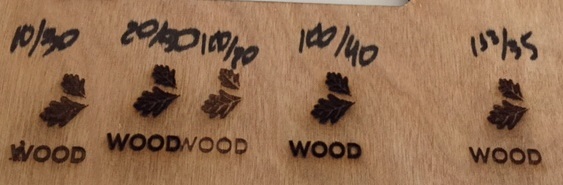
Next step would be to test different PWM frequencies. Higher frequency and feed produces deeper grooves with less burning, lower frequency and feed gets darker and better grayscale.
I got the C3D yesterday and I’m now playing with your modified $33 grbl-lpc. I’m having great results. Still tuning/learning the relations between feeds x speeds x freqs. I’ll post my results.
 and I’m loving it)

 I would say that 10% bouncing up to 5ma is a problem. IMO, 100% is around 20ma on a K40. Of course, I only have experience with mine.