Hi
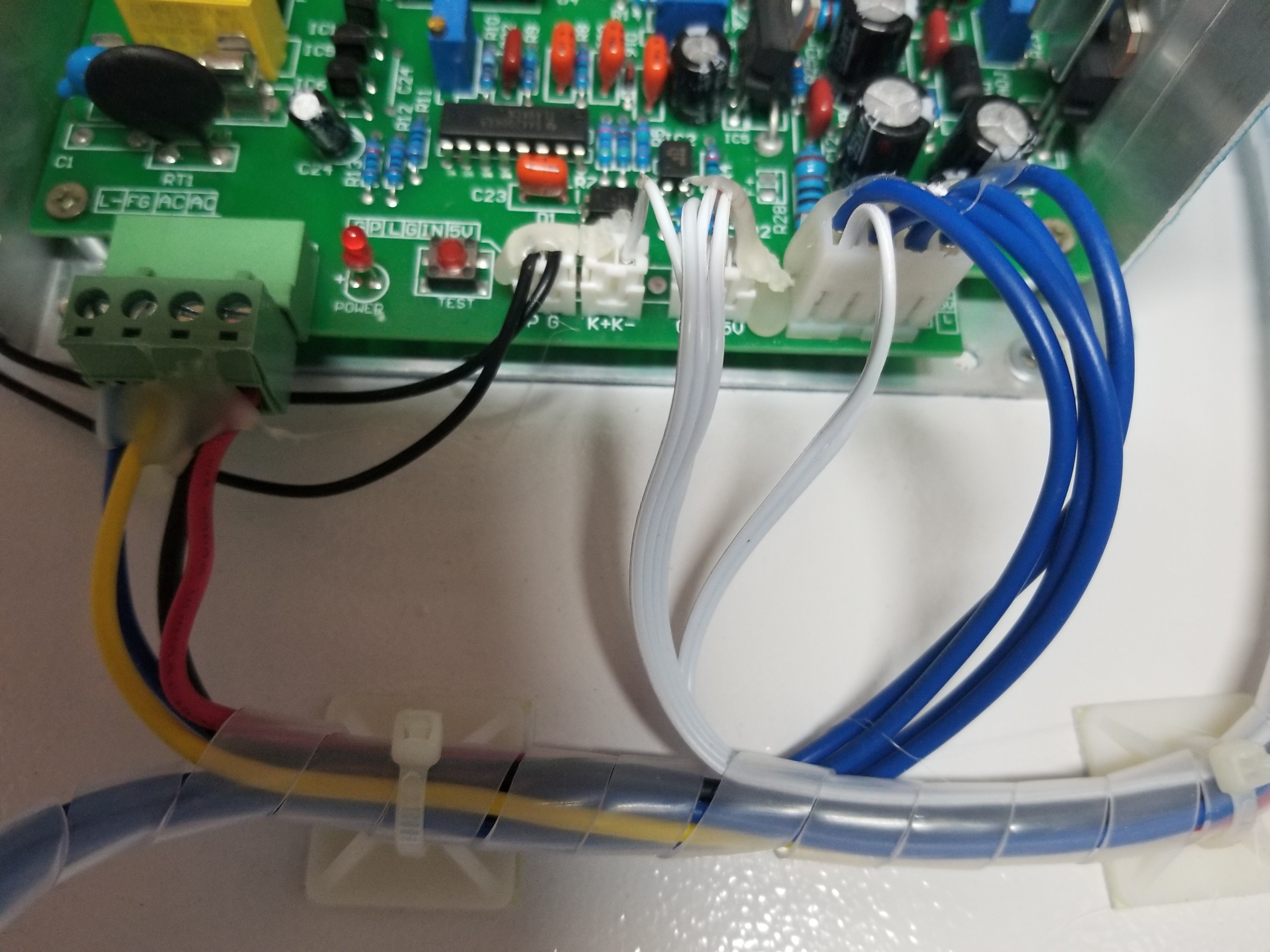
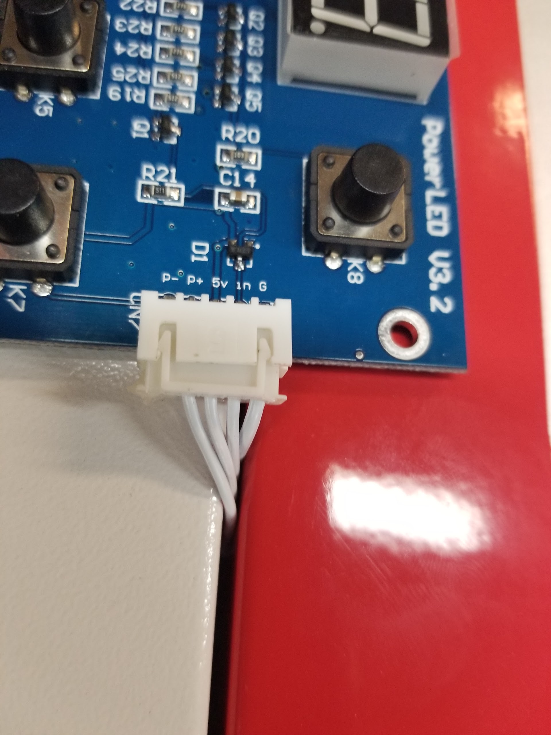
Another newbie here. I just purchased my K40, everything seems to work except that it won’t fire from the test button on top of machine (it does fire from PS test button). On the PS, there is no wire attached to the K+. Also on the control panel board, the 5 pin plug has no wire attached to the P-.
My question is, could this missing wire be the issue?
If so, does the K+ connect to the P- ?
Thanks for any thoughts or assistance!
Mark
Mark, I will look at this in the am…
#K40LPS_K+/K-Reversed
I do not have a _digital panel nor a wiring diagram for that panel so some of this is based on what I know the Laser Power Supply (LPS) needs.
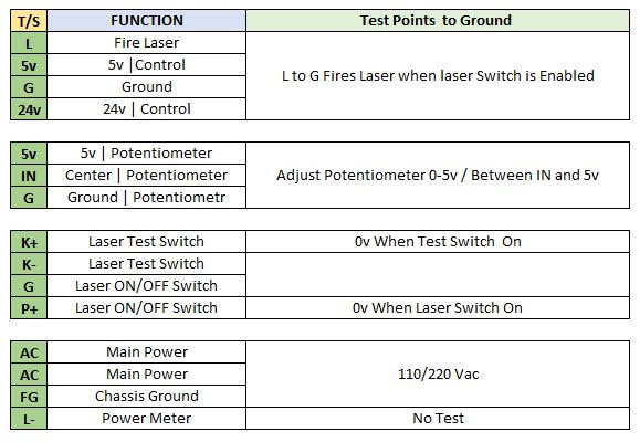
See the chart below.
… K+ is grounded when the TEST sw is pushed.
… For the LPS to fire P+ must also be at ground which is usually provided by the Laser Enable being switched on.
Label K+,K- reversed
I just had a case where the K+ and K- was reversed on the silkscreen. Yours seems to be the same i.e. reversed? The silk screen is wrong, not what is on the pin. So (K- = K+) and (K+ = K-).
A picture of a supply with the correct silkscreen:

Conclusion
So what this tells me is that the K- is what is actually left unconnected and since K- is just ground it probably is derived from another ground up on the panel. Perhaps the G on the 3 pin connector to the right of the K+K- connector. I do not think wiring is your problem.
Test LPS Controls
If you have and can use a DVM, on the volts scale:
1)…Check the voltage on P+ with the “laser Switch” on.
2)…Check the voltage on K+ when the “Test” switch is pushed.
The chart below shows the values.
Verify Coolant flow switch
I notice that the P/G plug has 2x black wires not going to the panel?
I am guessing this is going to a waterflow sensor and then to the panel somehow?
3). Do you have a water flow sensor?
4). Is the pump working and are you running coolant through the tube?
- Probably unrelated to this problem*
5). Where does the white wire connected to the rightmost connector go, that is 24VDC?
Report Back
… Please report back the answers to the above questions using their # for reference.
… Please post a picture of any water sensor you find.
@donkjr
Thanks Don
#1. I am showing 5v on the P+ pin to ground, (I think this is incorrect from your chart?).
#2. I didn’t try this yet, as you mentioned my silk screen appears to be labeled backwards. Should I actually be testing K- or the K+ in this case?
#3. I do have a water flow sensor (yes, the 2 black wires you noticed go to it).
#4. The pump is working and I am running coolant/water through it.
#5. Those wires go to a LED strip light in the cutting area.
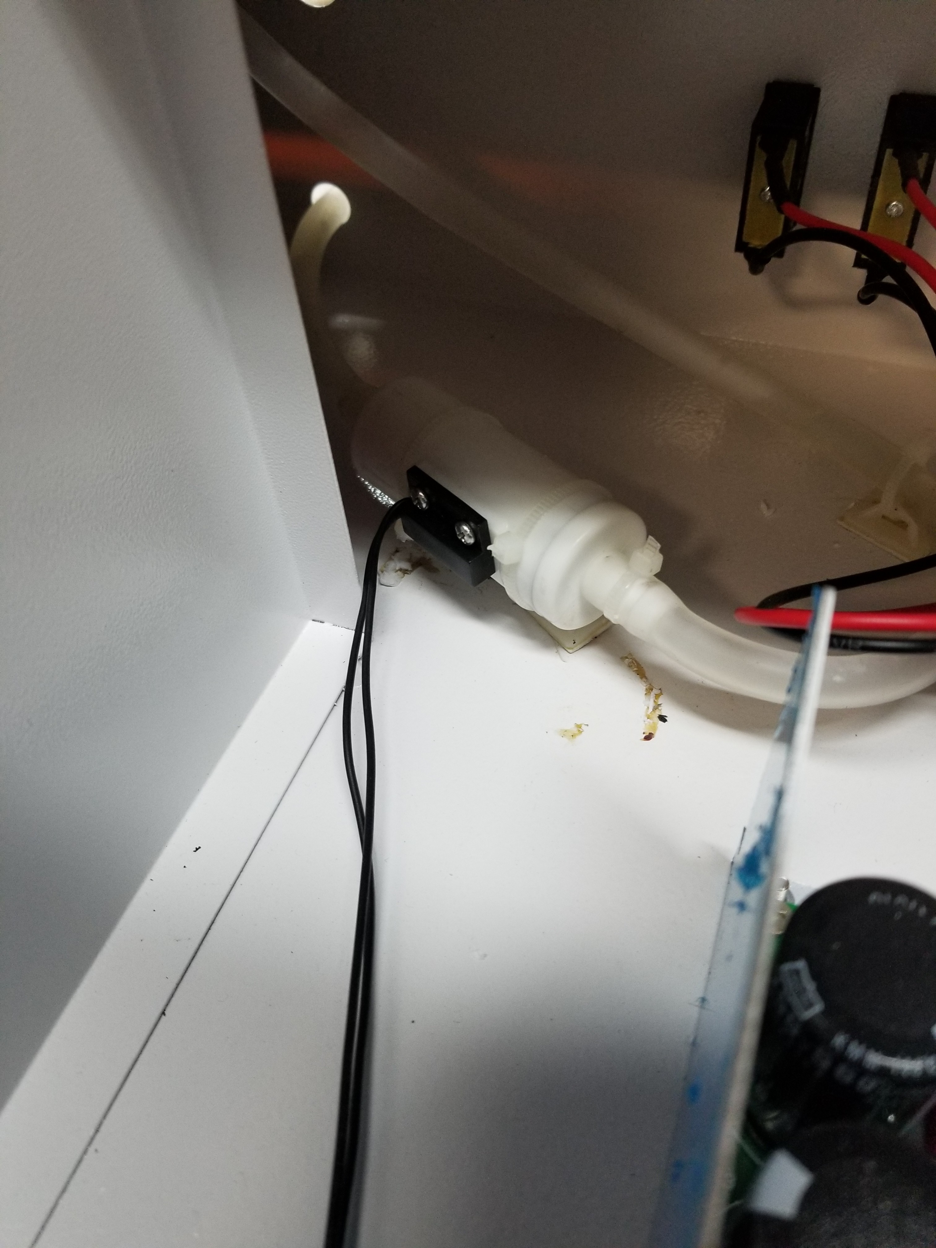
Below is picture of my water sensor. I wasn’t sure if the test button on the PS would fire if the water sensor was not working?
Also, FYI I have not tried to “run” the laser yet as to cut from a file. If this is just an issue with the control panel test fire button, would I still be able to cut from a file?
Also, is the digital control panel considered to be inferior to the analog type?
Thanks again for your help!
Mark
#1. I am showing 5v on the P+ pin to ground, (I think this is incorrect from your chart?).
Ans: This should be 0V or ground if the sensor and the “Laser Switch” is on.
I wasn’t sure if the test button on the PS would fire if the water sensor was not working?
Ans: the test button down on the supply bypasses everything. Yes the laser will fire irrespective of the control signals.
Cause
I am guessing that your water sensor is not working.
Test
#6. disconnect the connector to P/G from the LPS.
#6a. While the machine is pumping water read the sensor leads with a DVM on the Ohm’s scale. If it reads 0 Ohms then it is ok. If not then something is wrong with it and you need not go any further until that is resolved.
#6b. CAUTION this test MAY FIRE THE LASER so insure that you are protected.
Insure that machine is on and Laser Enable switch is on.
Briefly connect the P pin to the G pin on that same connector on the LPS and see if laser fires?
If not… we will continue with another test. If so then there is something wrong with the water sensor or its wiring.
Let me know the results of these tests.
I think I was doing this as you were typing : ) It appears to me to be a NO switch and water flow should close it via a magnet. I used a meter for continuity and my switch was not closing when I turned the water pump on. So I used an external magnet on the switch and the test fire button is now working.
Great information to know about the PS . I am so glad I found this group.
Do you have any thoughts on the control panel digital vs. analog?
Thanks
Mark
@Mark_McCarty so you have a bad switch? Bypassing it is a bad idea cause it doesn’t take much loss of coolant to fry a tube.
Get a new one from the vendor?
There are various opinions on the digital panel.
Some like it, I do not it seems like overkill just to adjust a voltage on the the LPS.
The digital power is a relative setting. Its a digital representation of the LPS power setting (actually the IN value). That’s ok because I have a voltmeter on my pot that does the same. But the digital meter alone does not tell you what the lasers power is actually doing. It only tells you what it is set to.
There is no actual power meter. A current meter is very useful to watch the lasers behavior since it monitors the current in the tube. The current in lasers for a given output will vary as they age. Also the dynamic movement of the meter can tell you things about the lasers power output and is often useful when troubleshooting.
Example; with a power setting of 10 [arbitrary # used in example] the laser might draw 8ma and cut 1/4" mdf in 2 passes. As the laser ages that same setting results in a current of 5ma and two passes will no longer cut through the material. Without a current meter you don’t know enough to turn the power up and to what value.
You can just add an milli-amp meter and keep the digital power control or you can add a pot and meter like the vintage machines.
A secondary consideration is that we do not have any schematics on the digital board and I suspect it has an embedded controller so we do not have the firmware. They seem to have a high failure rate but you can get a replacement for $20 on eBay.
@donkjr
I actually think the problem is with the part in the flow “tube” not moving or not being strong enough to activate the switch (since an auxiliary magnet works with switch).
Either way, my bypass is temporary. I will get a proper working flow sensor.
Thanks for the insight on the analog vs. digital. I can see where it is worth it to add in a mA meter.
If/when the digital board goes out, $20 is cheap enough or may look into to going old school : )
Still much to learn, but I was able to load a file and cut a square! I’m off to the races.
Thanks again for your input and great website, I still have a lot of reading to do.
Mark