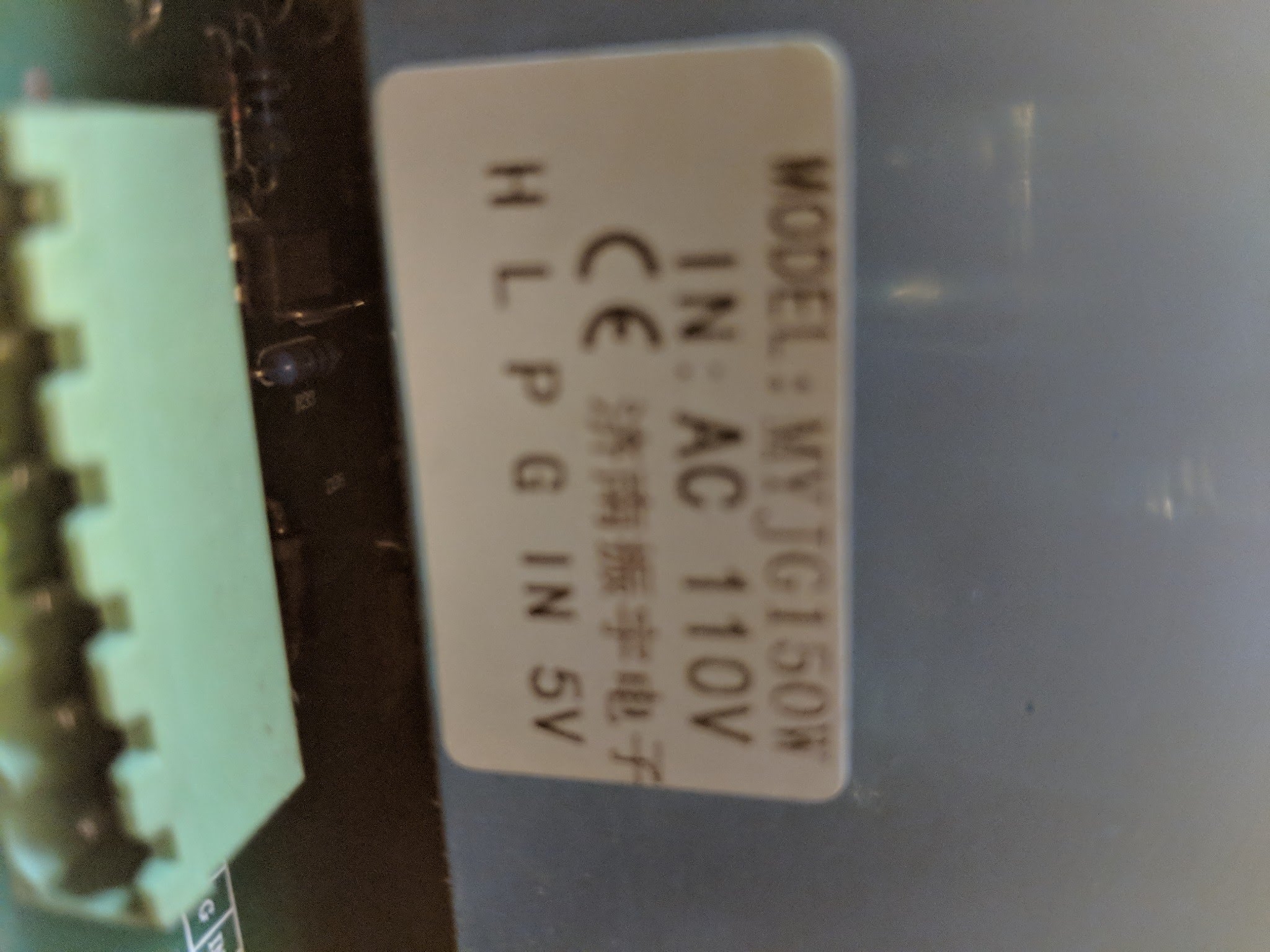
Hey guys, I recently bought a used red and black 500x700 cutter. The machine didn’t have the controller so I am attempting to convert it to smoothieware or grbl. It’s a 130w tube with 150w psu, I’ve wired it like I did with my k40 or as best I can due to the differences between the 40w psu and the 150w.
I wired in a pot and connected L to my smoothieboard. It moves and homes fine, test fire works but when I try to run a job it seems to short out the 12v psu I have driving my smoothieboard. The board doesn’t seem affected but the psu light flickers on and off and the tube doesn’t fire. Every time the tube should fire the psu dies.
Only things connected to the psu is leds and the board which I already tried removing the leds to see if power was leaking.
Another thing I noticed when I connect P and G the laser fires right away…I thought p was the interlock.
I’m kind of lost now on what to do or check. Any suggestions?
I will get some pictures tonight after work though it’s a huge mess right now until I have it working correctly.
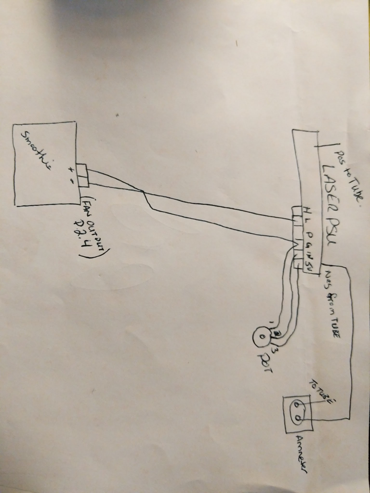
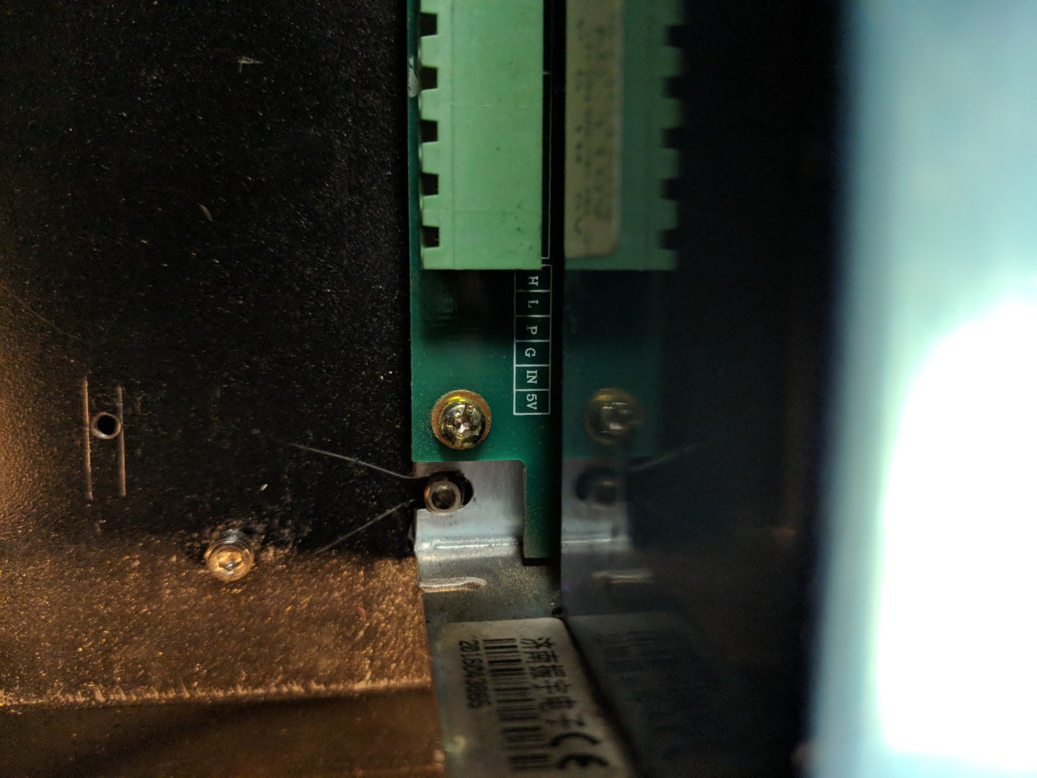
I did read on another forum that a pot and pwm isn’t possible for my supply. It has 3 pins like on a regular psu for gnd/N/L then one connector with T,L,P,G, IN,5V. Which is different from my k40psu.
Need to know exactly what pins on what smoothie your using.
The L pin needs a ground through a mosfets drain. The + on most smoothie mosfets is VDD so in your schematic. In your drawing you may be grounding the VDD supply.
Also insure that the L pin on the rightmost connector is left open.
It’s actually mks sbase not genuine smoothie but pins should be the same. Using p2.4 as stated above and it’s ground. They are connected(tried reversing the wires also ) to L and G on lps.
@Chris_Menchions I suggest posting a picture of the connectors on your LPS, that will help me get oriented.
The only thing that I see that may be a problem is the output (PWM) on your MKS Sbase P2.4. Often the + is pulled up to VDD on the card. In your drawing you have it connected to GND and that would connect the the VDD + pullup to the LPS gnd. I am not sure about this because I do not have a MKS schematic, do you?
You may not want to connect the + P2.4 at all and use another verified ground from elsewhere on the MKS board.
With the machines power off, using a DVM on ohms, see if the + P2.4 is connected to ground or to VDD through some resistance.
@Chris_Menchions … and a picture of the LPS label with part # might help.
I also noticed when rereading your post: Another thing I noticed when I connect P and G the laser fires right away…I thought p was the interlock.
Does this happen when there is nothing else connected to the connector on L or H?


 I’ll do the pot to 5v in G firstly.