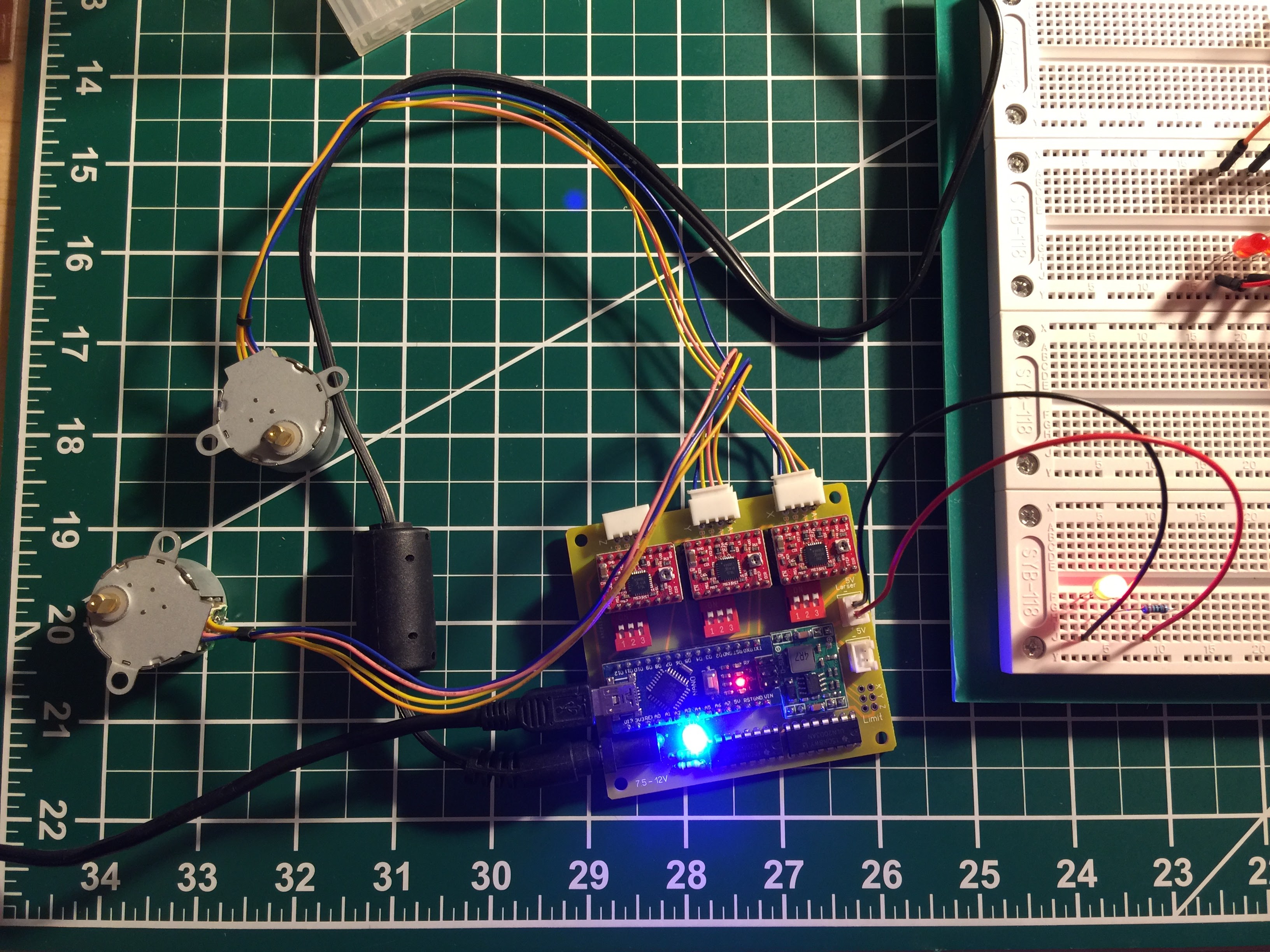
I have a K40 Laser and I want to switch out the lovely controller board with a GRBL controlled cheapo China board. China meets China. My test motors are working fine but the LED does not seem to function using the M3 and M5 commands. I see D12 on the Arduino changing its state but I don’t see the Darlington on the bottom left doing anything with the LED on my bread board. Broken Darlinton or am I doing something wrong?
I’m wondering if this little board is capable of doing more than just laser on laser off? I saw some very impressive 8 bit laser control using the smoothie board to essentially engrave 2.5D into wood. Did anyone try engraving 2.5D engraving with GRBL before?
EDIT: Using the Pin D11 controlled by VARIABLE_SPINDLE it is possible to set the PWM for the laser diode. I will have to rewire the pins a bit to get the pulse generated by D11 out of the laser connector.
However: Now I have variable spindle speed as a PWM input for the laser but the laser needs to be controlled by gcode. So If I want to engrave an image in 8-10 bit grey scale or even a 2.5D object… what does the g-gode look like? How can it be fast enough to get all the data over to GRBL and still maintain a seasonably fast engraving speed?
I’m not sure what software you’re using, but if it’s written for the K40, the Laser Operate (LO) is inverted, so you need to set the darlington up as a pull down against a pullup resistor. It needs to be 5v, not 3.3v so source the V+ accordingly.
The K40 supply fire circuit has 2 pins, one is gnd and the other is an opto isolator emitter with pullup resistor, so you need to pull the input to ground to fire.
I’ve not played with the engraving much at all, but from what I see of it, it’s quite slow compared to the M2/Laserdrw setup.
Again, just from what I’ve seen, the G code is speed, power and distance to change on each line, It makes for a lengthy set.
There’s several expert engravers on here, that can give you the info on the engraving setup. I’m just a hardware guy.
@Timo_Birnschein Some great information on using GRBL with lasers can be found at http://www.picengrave.com/forum/
John and Jeff over there are great guys and respond quickly. They do not have a lot of experience with CO2 lasers since their work is with solid state lasers, but they know how things work at the GRBL level.
I figured out how to get a the laser enable pin as well as the laser intensity pin controlled by GRBL 0.9. For the intensity control using PWM I had to modify GRBL a bit because the PWM for a motor spindle is growing but the PWM for the laser intensity on the K40 seems to be getting smaller. I hope that’s correct, because I have a multimeter connected to the poti on my K40 laser cutter and the higher the voltage the smaller the cutting power. OK, so I inverted the PWM values.
What works so far (using GRBL 0.9 running on an Arduino Nano):
Motor control on two axis
Laser Enable as active low on Digital Pin 13
Laser Intensity with inverted PWM on Digital Pin 11
Very (VERY!) slow 2.5D engraving as prove of concept on my table. I don’t yet know how to speed up the individual lines. I guess that requires a faster processor, more RAM and a function that controls the PWM intensity per step on a line and not per little vector piece.
Next up is a custom board to transplant the GRBL board into the K40 and first tests.