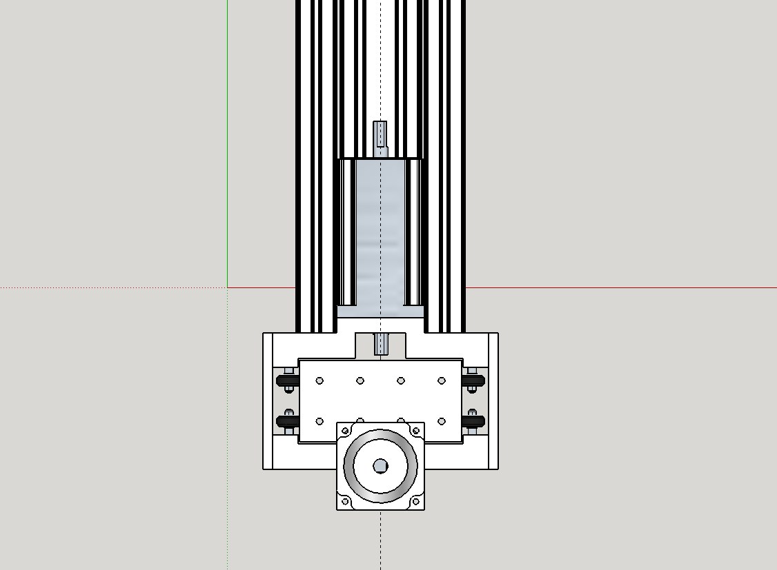
hey guys i had an idea to move the whole Y gantry up and down for Z movement and would like some opinions
Couldn’t be any harder than squaring the x axis surely? actually thinking about it as long as the x axis rails are level and parallel using the inductance sensors I can’t see it being too difficult at all
depends which way you orientate the machine i was going to make X the short axis from front to back and Y the long axis side to side like this one http://youtu.be/PoRKGFPmRn0 but with the whole Y gantry going up and down
ok yes my bad you’re right of course but forgetting my stupidity on the orientation would making the gantry raise an lower be a good idea i was thinking it would reduce twisting force from having Z lower and acting like a lever
+Peter van der Walt What you are really losing is the gantry being solid itself. With the top beam moving up and down the gantry is no longer an integral structural member. Then there is the additional mass the Z axis is moving to consider too. Moving less mass is generally considered preferable. X has no choice but to move everything in a moving gantry, Y has to move Z and itself, but Z usually only has to move itself.
What you potentially gain is a lower center of gravity when Z is down. Although with the motors located on the top I’m not sure how much gain is being had with this design.
Put a fixed beam on top of those two X axis uprights to box it, and move the motors to the bottom and I would like this design a bit better myself. Not enough to build it, but I’d like it a bit more mechanically.
Thats really interesting Paul the initial idea for this came because i’m going to need 2 - 3 foot of Z travel (thinking of carving rocking horses) and just thought the lever action on a 5 axis Z plate that long would produce more flex as for moving the motors to the bottom i don’t see a problem with that as long as it doesn’t stop the gantry coming low enough
also there would be a motor at each end to help with lifting the mass
@Gary_Wilson
There are force calculators online for lead screws and torque. I wouldn’t be surprised if your setup could lift the front end of a car up. Are you using ball screws? If you are then your setup might be a problem. Because once you power your machine off your Y axis will fall down, unless you remember to block it up. Ball screws do not hold position like other screws do. Which isn’t a problem while you’re running because steppers hold strong. In fact holding is the strongest thing that stepper motors do. Your best bet would be a multistart thread. Multistarts move fast, and hold too. They are less efficient than ballscrews though.
still considering the options Paul but having the gantry down when not in use wouldn’t be a problem
@Gary_Wilson You could have stops on your pillars so the gantry couldn’t go past them I suppose. Your spindle falling to the bed would be a problem with a tool in it.
Also Paul the 2 X axis would be coupled together under the table I just haven’t got that far with the model
@Gary_Wilson
I figured they would be. The Y axis uprights still would not be rigidly boxed together even if they were though. You’re going to have to add some kind of a stretcher bracing on the top. Well, you don’t have to, but it would help keep those uprights aligned.
Reducing the height of the gantry while machining over your stock material and/or fixtures could be a potential issue as well, with clearances. It would stress me out, I would be constantly worrying about it crashing.
What do you gain by making the translational mechanical components heavier and more complicated?
What purpose does a variable gantry bridge height serve in machining?
As far as the math goes, increasing the mass of the translational element also greatly increases the work it takes to move that mass X distance. (W=mad)
Just a thought
Charlie
@Charlie_Gwathney the crashing thing is the thing that is turning me off the idea tbh i think you are right when you say there could be clearance issues. thanks for the input.
Other than the nonstandard xy orientation I think it’s a nice way out
I think your asking for trouble. I’m assuming a z drive for each side. I did a stepper for each side of my x axis. Even doing a homing each side your relaying on never losing a step on one side. I ended up coupling both sides with chain and using only one motor. Once sq’ed up it never gets out of sink.