Hey @Brook_Drumm , I’m thinking of cutting out the inside of the fuselage as follows to make designing the framing easier. The idea is that the internal framing will fit inside the cavity. This will affect the ability to print in a spiral right? What are your thoughts?
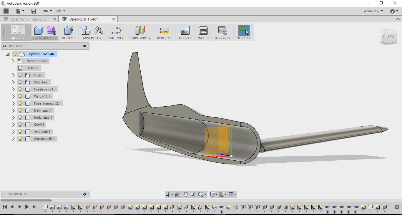
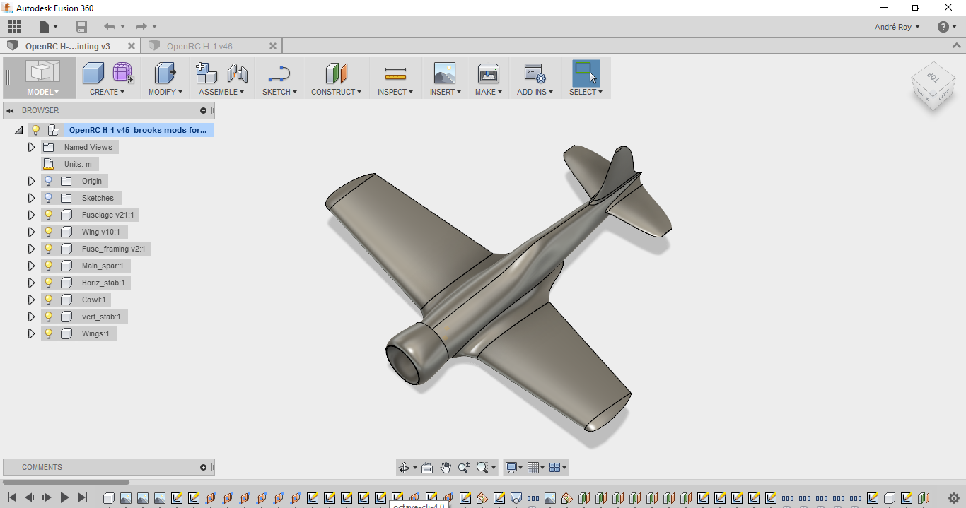
I mirrored the two halves to make a whole fuselage then just exported the solid. Slicing as a spiral print is simple but we do need another solution to give it rigidity. I though about doing what you show here, then cutting a hairline slot down the entire length… That will slice as a spiral print- printing the inside and outside walls in one loop… If the slot is , say, .3mm wide, the loops will likely fuse together. The problem I see is that you would have to have the inside cutout always intersect the outside wall with around 1.9mm total thickness- measured from the outside wall to the inside wall. To do this, we will have to get creative with using intersecting objects - designing the inside structure separately and oversized with 1mm walls extending out at 45 degree angles at each corner of the inside box and making them way to long, then placing the two objects over each other and cutting where they overlap. The fuselage will have to be shelled to a 1mm thickness first. This should leave the extending corner walls with the exact shape of the interior shape. Then we combine the two objects to make one object and decide where we cut it to make the whole thing one continuous loop. The supporting corner walls may have to be double thickness with a thin cutout in the center to get the loop sorted out with filament fusing together in the connecting points. It’s hard to explain and will be tricky but i think its doable. I’ll run a test and design an example. If it works, it should solve the problem with warping on the flat sections of the wings due to cooling. This method may be the key to designing very large objects intended to print with a spiral print. This will speed the print immensely and we may end up with a airworthy frame all 3D printed.
The model of the printable plane I bought had some very clever design to reinforce the thin walls but I’m looking for a shortcut that will work with my limited skills 
Since the inside box cutout will be printed nose-down, the back wall will need to be a wedge of pyramid to prevent the need for bridging. The inner walls will take the place of spars in the wings and fuselage. This could really be a huge step forward.
I’ll draw something up to prove my theory.
Brook
I think my problem is I’m not a highly skilled parametric CAD guy, I’m basically a noob and my limitations and lack of a network of CAD experts to talk to kind of limits the solutions I come up with. (Always seeking collaboration or just discussion)
I was reading what you were saying carefully. Your solution, splitting the mesh is pretty clever, never crossed my mind. It got me thinking about what I had proposed; you mentioned needing to shell the fuselage, and I came up with an idea for how to design for a single wall shell pretty easy (if it’s workable). I didn’t know how, which is why I was avoiding it.
I bet if I can do a shell operator on the fuselage shape, and use that as a boolean cut operator to “shave off” say 1mm thick skin (+ tolerance) off the shape. I could then use that shaved form to cut bulkhead “slices”, through which carbon fibre spars can run through to create a frame. Something like this: http://tinyurl.com/gpf4gr6
We’d 3D print the bulkheads (assuming they’d take the loads), and insert them into the shell and glue it in place. The bulkheads are bonded to the carbon fibre spars that creates the frame that bears all of the aerodynamic and inertial loads acting on the plane.
If anyone is a CAD expert out there, we could use some peer review on the drawings to help us improve.
I went over it with Brian today. He got excited about my idea and spit out a test print model in about 5 minutes. Once I nail down the method and what size of a split that will fuse together even though the slicer paths it as a void, I’ll draw up the model with a large box for electronics and weight savings and include a void for the spar. I ordered some carbon fiber rod too.
Should be fun!
Btw, I have family time off scheduled this week but I’ll noodle on it a bit
Brook
Looking forward to seeing what you’ve come up with. Continuing to brainstorm a bit ;). If the fuse was printed as a 1 layer shell, we could have bulkheads at every seam, every 1 or 2 feet. They’d be easy to insert at the seams.
Hey Andre, I’d be happy to take a look at any drawings you have for this (full disclosure: I work for http://www.graitec.co.uk who are an Autodesk Platinum reseller, and whilst I don’t know Fusion 360 that well, I regularly train people using Autodesk Inventor/AutoCAD)
Cheers,
Alex.
Sweet, yeah I’ll definitely take any advice or tips from anyone much more experience with CAD than I.
I believe this link should give you access to the drawing. Let me know if it does not.