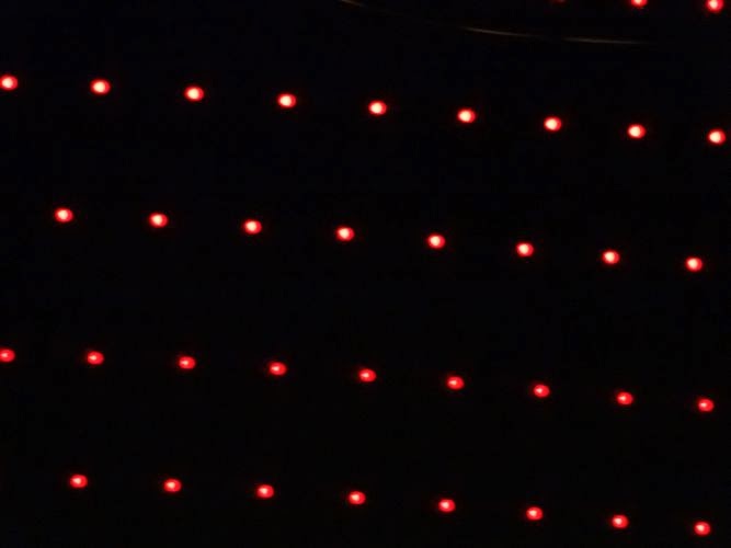
Here’s a TM1804 on the right, displaying the constant value (30,0,0) - a little more than 10% intensity on one channel. You can see the PWM. I swung the lens of a point and shoot camera horizontally while it was taking a relatively long exposure (due to being rather dark overall). The LEDs were pretty much vertical - the horizontal offset between the rows is due to the asynchronous PWM on adjacent pixels.
On the left is two hoops; the hoop on the right is changing from blue to red as the lens swings vertically. You can see the changing periods of the PWM as the intensity changes (looking closely).
The 400 Hz PWM on these chips (and the 2811) make them very visible as your eyes scan past. It’s easier to see with a mirror (wiggle it), or you can use a camera which has some long exposure mode (this was maybe 1/4 sec).
By the way, in the picture to the right, the pixels are about 10cm (4") apart vertically. So at the unknown rate that I was swinging the camera during the exposure, the PWM cycles are about probably about 5 cm apart visually.
The intensity of 30/255 is around 12%, which would cause one to expect the trails to be 6mm wide; the pixel LED is 8mm wide in a translucent 12mm base so I would have expected the dots to look slightly elongated horizontally but do not see that (slight) effect. The camera focus was probably off, tho, blurring the pixel shape.
Using a 4KHz PWM rate (8806), or about 10 times as fast, the PWM cycle would have been more like 5mm wide visually in this particular photo, which is smaller than the pixel, so I would expect it to really look dimmed but pretty continuous rather than as discrete dots. I hope to have a new picture later to test and demo that.
