I have Smoothieboard configured and moving my GWEIKE laser axis OK. Axis are calibrated.
Last issue is connecting the 60W Cloudray Laser Power Supply:
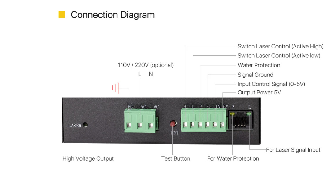
I am using pin 2.4 and ground for PWM control connected per the Smoothieboard laser instructions.
I put a jumper from Power supply “5V” to Power Supply “IN” per the diagram
Power supply “G” is connected to Smoothieboard GND on the same row of pins as pin 2.4
Power supply “G” is also connected to DOOR SWITCH (NO), Estop button (NC), Flow Switch (NO)
Other terminal of the Flow switch is connected to Power Supply “P” (So the door switch, Estop button, Flow Switch are all in series, door must be closed, Estop switch in normal position, and flow switch closed to enable the laser Power Supply)
Power supply “L” is connected to pin 2.4
I have a Laser Fire Test button (NO) Across Laser Power Supply “G” and Laser Power Supply “L”
What happens is, simply when I close the door, the laser fires full power with no command from Lightburn. That tells me that pin 2.4 is LOW and firing the laser. So, I took the wire off the laser power supply “L” that goes to Smoothieboard 2.4. Closed the door, laser did not fire. I pressed the laser fire test button and the laser fired. Which I would expect. I measure the voltage from Laser Power Supply “G” to the wire going to Smoothieboard 2.4 and I measure 3.3VDC, so techincally it is “high” but wondering if not high enough for the laser power supply?
OR
I don’t have something configured right in my config file.
I tried searching on line for an example of a CloudRay Laser Power supply hook up and no luck, hence my post here.
So close. Hopefully one of you can help me out.
Thanks!
Marty
Here is a the laser section of my current config file (I was going to file attache but says New Users can’t attach):
## Laser module configuration
laser_module_enable                         true			# Whether to activate the laser module at all. All configuration is                                                            # ignored if false.
laser_module_pin                            2.4o!			# this pin will be PWMed to control the laser. Only P2.0 - P2.5, P1.18, P1.20, P1.21, P1.23, P1.24, P1.26, P3.25, P3.26
															# can be used since laser requires hardware PWM o!=open drain invertedfx
laser_module_maximum_power                  1.0             # this is the maximum duty cycle that will be applied to the laser
laser_module_minimum_power                  0.0             # This is a value just below the minimum duty cycle that keeps the laser					# active without actually burning.
laser_module_default_power                  0.5             # This is the default laser power that will be used for cuts if a power has not been specified.  The value is a scale between
															# the maximum and minimum power levels specified above
laser_module_pwm_period                     200				# this sets the pwm frequency as the period in microseconds
switch.laserfire.enable						true
#switch.laserfire.output_pin				2.4!^			#connect to laser PSU fire (!^ if to active low, !v if to active high)
switch.laserfire.output_type				digital			#
switch.laserfire.input_on_comand			M3				#turn on laser
switch.laserfire.input_off_command			M5				#turn off laser
Anyone help out or explain how smoothieboard controls this type of power supply? It appears to me that the IN of the power supply should be modulated using the 5V provided by the power supply. The L could be connected via G on the power supply via a TTL output on Smoothieboard to turn the power supply on or off and I could parallel across L and G with my normally open Test Fire switch.
If the above is true, how would the config file look?
Guidance appreciated. I do not want to damage the Smoothieboard so waiting on suggestions first.
I have tried searching the web but either I am not using the correct search words that will help me find what I’m looking for or its not out there?
Here is the circuit from the Laser Example in the Laser Guide and this is how I wired it. I found this excerpt from “Don’s Things” and it concurs with the example, so I must not have something configured right
" Predictable Digital Laser Power Control:
A better approach is to use the “L” input control signal. On some supplies this input can be found on the LPS DC connector and on others it is on both the DC connector and the center digital control connector. On other supplies the equivalent of “L” is TH or TL.
The “L” or TL control is a digital input that responds ONLY to ground to turn on the laser.
With a proper PWM signal connected to “L” and the "IN " line pulled to 5VDC (analog full on) the LaserPowerOut function becomes:
You can see that this configuration elliminates all the control errors outlined above.
Note : Proper PWM control using “L” is to ground the “L” pin during the PWM’s on period. An open drain or open collector is the best electronics circuit to use."
The L pin of your laser power supply acrivates the laser at a low (GND) signal. So you must use the mosfet output (minus pin) on the smoothieboard (green connector). The mosfets plus pin can stay unconnected, just GND of the LPS must be connected to GND of the Power IN of smoothieboard.The mosfet works like a switch between minus pin on green connector and GND of power in.
Optionally you can use the H pin (activate on high) on the power supply. This could be switched with positive logic level.
Claudio, thanks for the reply.
However, I am not following you. I need a PWM output to vary the Laser PSU intensity. The drawing is right out of the Smoothie manual. I an not using a mosfet, rather using the PWM signal to drive pin L.
It sounds like you are suggesting I connect to the 2.4 mosfet itself on the green phoenix connector? If so, I’m confused why they would provide that example in the manual and its configuration.
You do not need a mosfet. Any pin on Smoothie can be used to control these PSUs. If you want to control them with 5V instead of 3.3V ( which you don’t need to, they work fine at 3.3V ), you can use the pins in open-drain mode ( see the documentation on external drivers ).
Just control IN via one of the PWM pins on Smoothieboard, L or H with one of the non-pwm pins, and tie PSU ground and smoothie ground together, and you are good to go, it’s as simple as that.
Good morning Art. I thank you for the response. I am confused as to why my Cloudray Laser PSU is not working per the example in the documentation. Its as if pin 2.4 on the Smoothie board is grounding pin L on the laser PSU, or its state is opposite of what is required. I happen to be using pin 2.4 and the ground pin to the left of that row of pins. I configured the pin per the example.
What I was trying to explain is, that the L pin wants a inverted signal. 0V means laser on, 5V means laser of. You can invert the signal of pin 2.4 via the ! in the config file (like Arthur wrote), or you can just use the mosfet output, as this does invert the signal too (and works for PWM). The third option is to connect the logic level pin 2.4 to the H connector of the LPS (instead of L).
No way could I get it to work with just the one PWM Pin from Smoothie.
I did get it to work as Art suggested
Cloudray Laser PSU Connections:
IN - Smoothie Pin 2.4 (laser_module_pwm_pin)
G - Smoothie GND. Flow Switch, Door Switch, Estop N/C, Test Fire Switch (NO)
P - Flow Switch, Door Switch, Estop N/C
L - Test Fire Switch (NO)
H - Smoothie Pin 2.13 (switch.laserfire.output_pin)
Laser Enable Section of my Config File:
## Laser module configuration
laser_module_enable                          true            # Whether to activate the laser module at all. All configuration is
                                                              # ignored if false.
laser_module_pwm_pin                         2.4             # this pin will be PWMed to control the laser. Only P2.0 - P2.5, P1.18, P1.20, P1.21, P1.23, P1.24, P1.26, P3.25, P3.26
                                                              # can be used since laser requires hardware PWM o!=open drain inverted
laser_module_maximum_power                   1.0             # this is the maximum duty cycle that will be applied to the laser
laser_module_minimum_power                   0.0             # This is a value just below the minimum duty cycle that keeps the laser
                                                              # active without actually burning.
laser_module_default_power                   0.5             # This is the default laser power that will be used for cuts if a power has not been specified.  The value is a scale between
                                                              # the maximum and minimum power levels specified above
laser_module_pwm_period                      200              # this sets the pwm frequency as the period in microseconds
switch.laserfire.enable						true				#
switch.laserfire.output_pin					2.13!^				#connect to laser PSU fire (!^ if to active low, !v if to active high)
switch.laserfire.output_type				digital				#
switch.laserfire.input_on_comand			M3					#turn on laser
switch.laserfire.input_off_command			M5					#turn off laser
What no longer works is my TEST fire button which I had connected from Laser PSU “G” to Laser PSU “L”. The Laser PSU Test Switch does not work either. I’m guessing it has to do with no +5VDC source?
I wish there were a way in Lightburn to test fire the laser.
I wanted to share what worked with my Cloud Ray Laser PSU. Not sure I need the test fire switch as I have an LED Laser dot to use as a target and its pretty well aligned with the laser.
Thank you Art. I appreciate your responses and support. I’m not new to CNC conversions, I beta test for Centroid CNC, I help with their user support forums. I’ve done many CNC Machine conversions. This is my first with the Smoothieboard. I can appreciate how much work and effort you take to help the users. It helps make Smoothieboard successful.
I did want to bring my resolution so that others might find it beneficial should they have the Cloudray Laser Power Supply.
Now I need to figure out how to configure my 4th, what I would call “A” Axis. Simply a stepper motor driving a chuck at 1:1 withi 1000steps per rev…
Lewis, so what you are suggesting is that I can still wire in a potentiometer if desired. Test Fire is not something that will work with the current wiring. Not sure I need it anyway as I have a red dot led pointer that gives me close location to the laser beam.
@marty_in_mesa FYI @lewis_hamilton is a spammer, and has been permanently banned from MakerForums. His post has been deleted as a result, and I wanted to explain.