I’ve been using a Makerbase Smoothieboard in my heavily modified K40 laser for several years. I typically have been cutting light stuff so I never noticed this problem until yesterday, here goes:
I don’t get full power from the setup, and it’s because I’m not driving 5VDC from the analog out pin (1.23) for the K40’s PWM signal. I dug into it yesterday and have verified that at 100% power and a laser_module_maximum_power set to 1.0 that I only draw about 4ma current. When bypassing everything (basically giving 5V to the PWM input) I get expected laser power.
I can’t for the life of me figure this out and need help. The Smoothie docs suggest using pin 2.5 but that’s a 24VDC output which I think would fry the laser power supply if I drove the PWM with it.
Has anyone run into this before? I’d really appreciate any and all pointers. I’m pretty experienced with makeing and the whole 3Dprinter/laser/device control world, this one has me stumped.
What DC voltage does your 1.23 read at various levels of power?
If 1.23 is set up for PWM correctly then you should see a square wave whose duty cycle varies with %power.
The average voltage reading with a meter should vary as ((%power/100) * terminal voltage).
So if the PWM signal is 0-5v the 100% setting should read 5V and the 50% should be 2.5V (.5 * 5= 2.5).
My guess is the the 1.23 signal is not a 0-5V square wave signal.
1.23 isn’t an analog pin is it?? Should be a digital pin configured for PWM with the correct signal characteristics i.e. 0-5V square wave.
I’ve got 1.23 going to the PWM in on the laser power supply. When measured, a line drawn at 100% only hits about 2.5V, which is what is really weird. And more so, the only changes I can get power wise is if I drop to 10% - 20%, then it does reduce output. It’s perplexing for sure.
So when I read the Smoothie docs I see that the recommend using pin 2.5, which is hotend out running at 24V. Am I missing something? Should I be using pin 2.5 instead of 1.23? I selected 1.23 originally because of the voltage difference (and I use 1.25 I think for the laser on/off signal pin).
1:
1.1 By the PWM pin do you mean the IN pin?
1.2 What is that pin labeled on your LPS.
1.3 What LPS do you have?
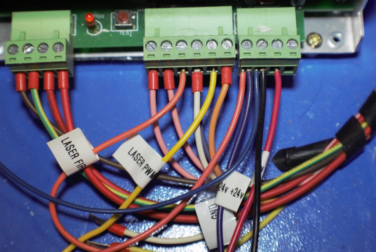
1.4 Please provide a picture of the input connectors on the LPS.
2:
2.1 How are you setting the power?
2.2 What kind of panel do you have?
digital
analog (pot).
2.3 Picture of your control panel, please.
If you are using the IN pin it must have a 0-5V signal to have the full range of power control. I am guessing that for some reason your PWM signal is 0-2.5V.
2.4 What is the PWM pin voltage when the machine is not running?
2.5 Are you saying that there is no change in the PWM voltage from 100% to 20% and then the voltage changes from 2.5 to 0 as you drop below 20%?
3:
For now, I would leave your setup as is until we understand it better.
Let’s not move anything yet. These outputs (2.5) can be set up as open-drain (with jumpers) and therefore in the right configuration, you should not have 24V on them.
3.1 Exactly what Makerbase board are you running?
4:
Some questions to help me provide you the right level of detail and troubleshooting suggestions.
*4.1 Do you have a DVM and know how to use it?
*4.2 What do you consider your electronics skill level to be?
*4.3 Do you have an oscilloscope and know how to use it?
Details on the PS would have helped, sorry for leaving that out. It’s an older PSU, I guess we’d call it type 1, with three green detachable power plugs. Panel is all digital, I put it in myself, took the potentiometer out of the chain so that the Smoothieboard is the only control for the power. I did leave the analog ammeter connected as a manual safety check. PWM is going to the IN port on the PS, the other out is going to the L / laser fire port. Pretty straightforward.
I have a true RMS DVM and a four channel 100MHz scope if I need to. I’ve been in electronics for decades. I design circuitry for a hobby, so my knowledge is pretty up there.
I missed the docs on the open drain ability of the outs - I am going to test that with my DVM (no laser connection of course) to see if I forgot that.
Smoothie config is as follows:
## Laser module configuration
# See http://smoothieware.org/laser
laser_module_enable                           true            # Whether to activate the laser module at all
laser_module_pwm_pin                          1.23            # This pin will be PWMed to control the laser.
                                                              # Only pins 2.0, 2.1, 2.2, 2.3, 2.4, 2.5, 1.18, 1.20, 1.21, 1.23, 1.24, 1.26, 3.25 and 3.26
                                                              # can be used since laser requires hardware PWM, see http://smoothieware.org/pinout
laser_module_ttl_pin 	                        1.22^           # This pin turns on when the laser turns on, and off when the laser turns off.
laser_module_maximum_power                    1.0             # This is the maximum duty cycle that will be applied to the laser
laser_module_minimum_power                    0.0             # This is a value just below the minimum duty cycle that keeps the laser
                                                              # active without actually burning.
laser_module_default_power                    0.3             # This is the default laser power that will be used for cuts if a power has not been specified.  The value is a scale between
                                                              # the maximum and minimum power levels specified above
laser_module_pwm_period                       200             # This sets the pwm frequency as the period in microseconds
#NOTE I had a value of 200 in the above line, which was well below the 20,000 HZ rating. Testing to see if this fixes power issues.

laser_module_maximum_s_value                  1.0             # Value of S code that will represent max power
Note that it’s actually valuable to leave the pot in place and use the smoothie in open drain; it lets you use the full range of power on the smoothie without aliasing. Set the pot to the maximum power you want to use, then use the full range of power on the smoothie, and you don’t have any additional aliasing.
Also keep in mind that full power to the typical K40 tube will burn it out. They aren’t really 40W tubes. More like 30W, so at 20KV you are looking at 15mA, maybe 18mA if you are lucky for max power for the tube.
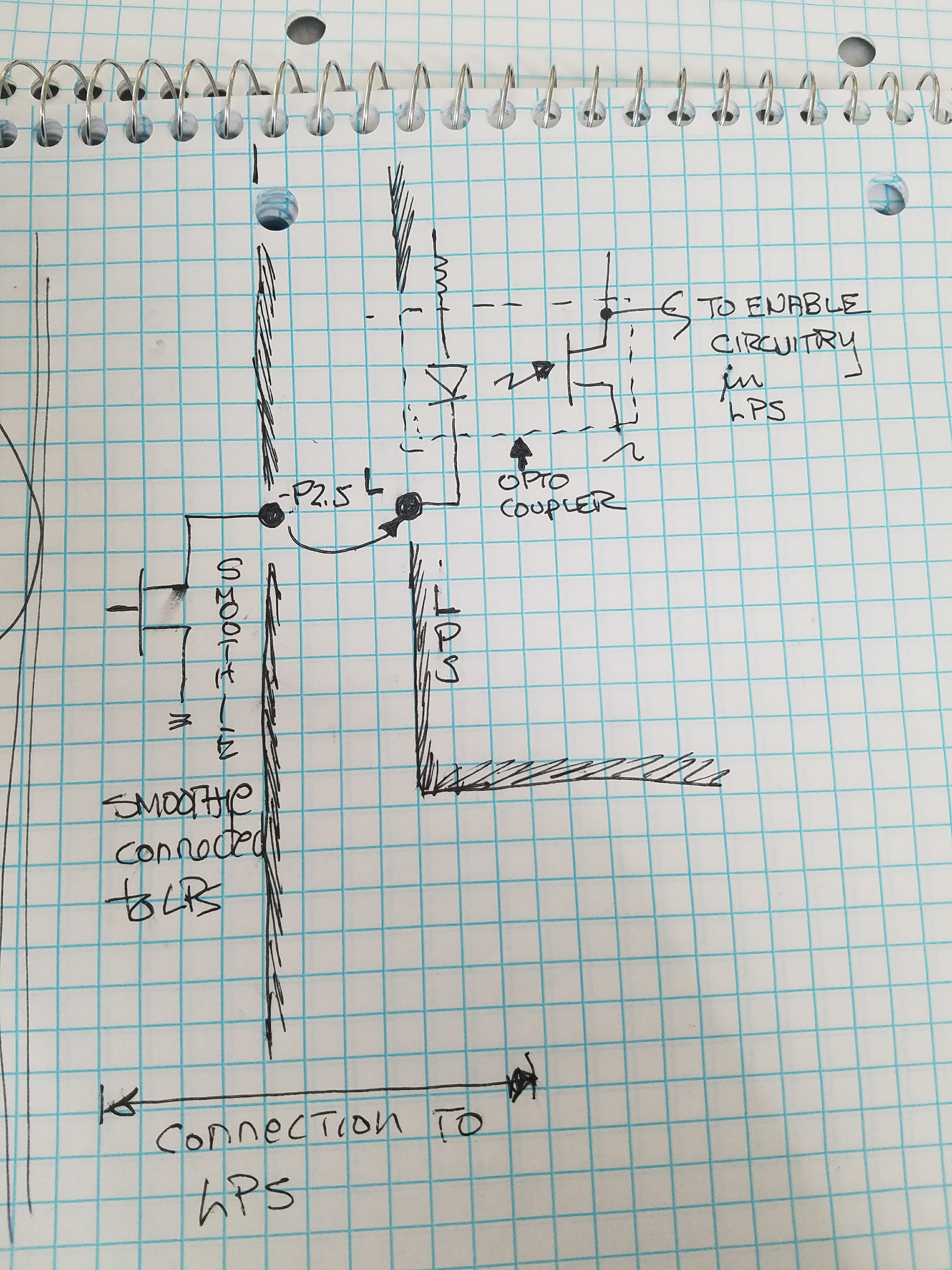
I also recommend to use the mosfet output pin 2.5. It’s important to understand that this output is a inverted open drain output, where you connect the L input of the LPS to the negative output of pin 2.5! The output will pull the L line down to GND when the PWM signal is on. It doesn’t matter that there is up to 24V on the positive pin, because you don’t connect anything there!
If you are using the L input of the LPS, you also need to have the pot on the IN pin to set the maximum power.
Now that I have a better idea of how you are currently connected.
My recommendation is the same as above:
Drive the LPS-L pin with the smoothies MOSFET P2.5.
Leave the pot in place connected to the IN pin to control the power manually.
Reconfigure your smoothie for this setup
Any open drain output that is also PWM capable should work. As @cprezzi points out you will connect to the drain (usually marked -) of the output mosfet which will, in turn, be connected to and pull the LPS-L line low. That is why there should not be any VBB voltage on that pin.
The Laser power supply input (L) is an optocoupler that expects its LED’s cathode to be grounded, that is why you should use an open drain. It’s important that there is no ground shift in this connection.
There are lots of good reasons to leave the pot connected to IN and control the L signal.
This older blog post may be helpful. Its the way many K40-smoothie configurations are set up. You don’t have a smoothie 5 but the same principles apply to your clone.
Maybe I wasn’t as clear as I thought I was: I have the laser firing using pin 1.22 (just fire enable, right?) and I want to have PWM controlled with (now) pin 2.5. I need PWM control so I don’t have to manually use the pot, especially for running jobs that have different output levels in one job.
So 1.23 turns the laser on/off and 2.5 sets the power - that’s what I’m after.
Does this make more sense? Sorry that I’m being dense here…
All the docs/posts I’ve read to date talk about using PWM for the fine control and L to turn it on off. You’re saying that I don’t need to do this - is there any specific docs on this? I’ve been thru all the example builds from the smoothieboard site and don’t see that.
Also, if I do use the L as the drive pin wouldn’t the PWM pin still require either a +5 or gnd for the tube to operate?
Well then, you did not read my blog post cited above?
I believe what you need is in that post.
I and many others have been using this configuration for years…
When the smoothie 2.5 pin is connected to the LPS-L pin it is configured as PWM. Therefore the signal on LPS-L is now the PWM and on/off laser control from the controller. The POT voltage is the coarse control of the LPS on the LPS-IN pin.
The OPEN DRAIN configuration provides a ground to the cathode of the LPS-L input optocouplers LED which turns the LED on, turning the laser on. When the LPS-L signal is not asserted (no PWM) the LPS-L = high resistance, the diode, and therefore the laser is off.
Thanks again, I really appreciate this! I had a prob getting to the original post, I think the link is to the post owner’s edit view - can you resend that link as a viewer not editor?
I get what you’re saying with this - forget PWM and use it as a coarse grained power setting, relying on the fire pin to control the operation. I’m now wondering what use the PWM input on the power supply is in relationship to the fire pin. I’ll dig deeper into that post and any others I can dig into.
Not sure how that happened?
Here it is, the post owner is me
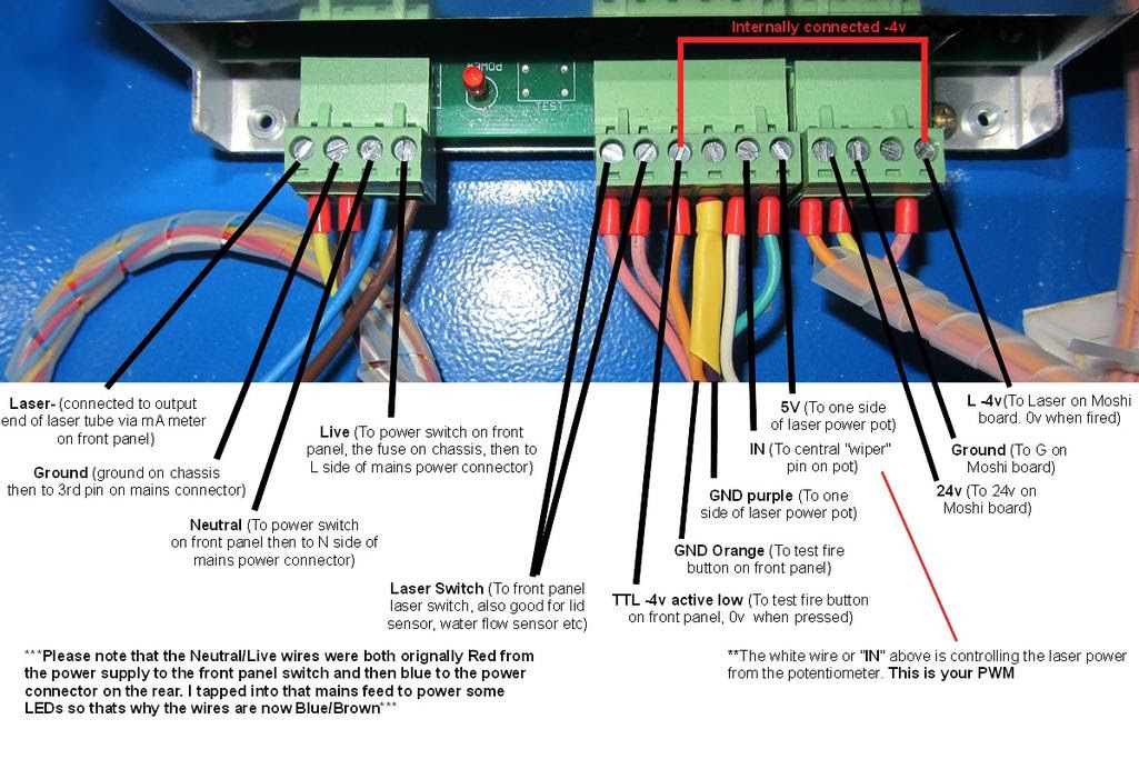
I suddenly realize looking back at your photo that you call what is normally IN = “PWM”.
The IN [your PWM] will set the max power with the pot and the L pin [not connected in your photo] will provide the PWM. The Fire pin is used for interlocks and the Laser Test switch and not used for PWM.*
The L pin is the rightmost connection on the rightmost connector.