Hello again. Again I’m in need of help with the setup of my K40. I’m amazed at how much I’ve been able to improve its quality. Unfortunately now I’m stuck.
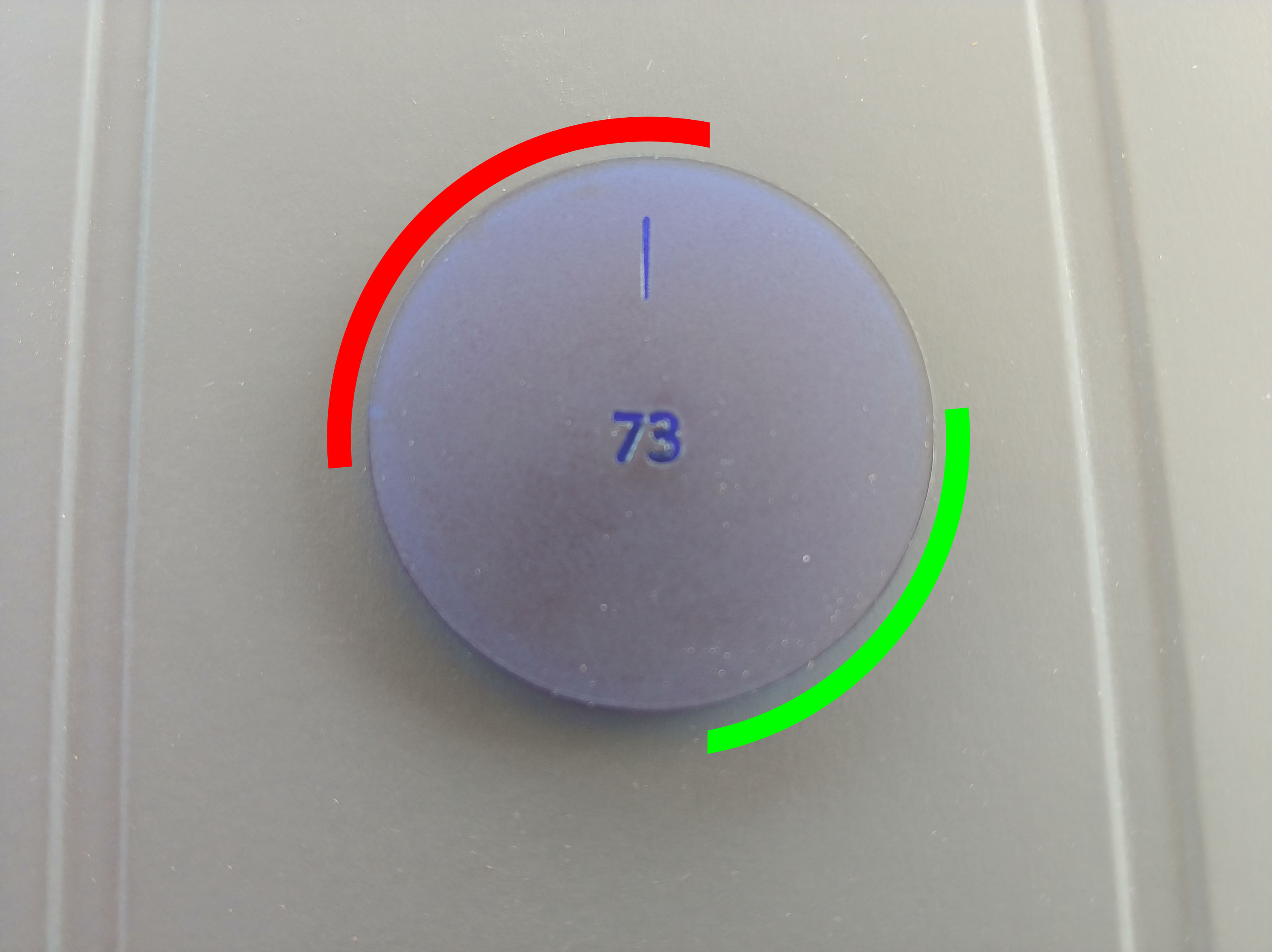
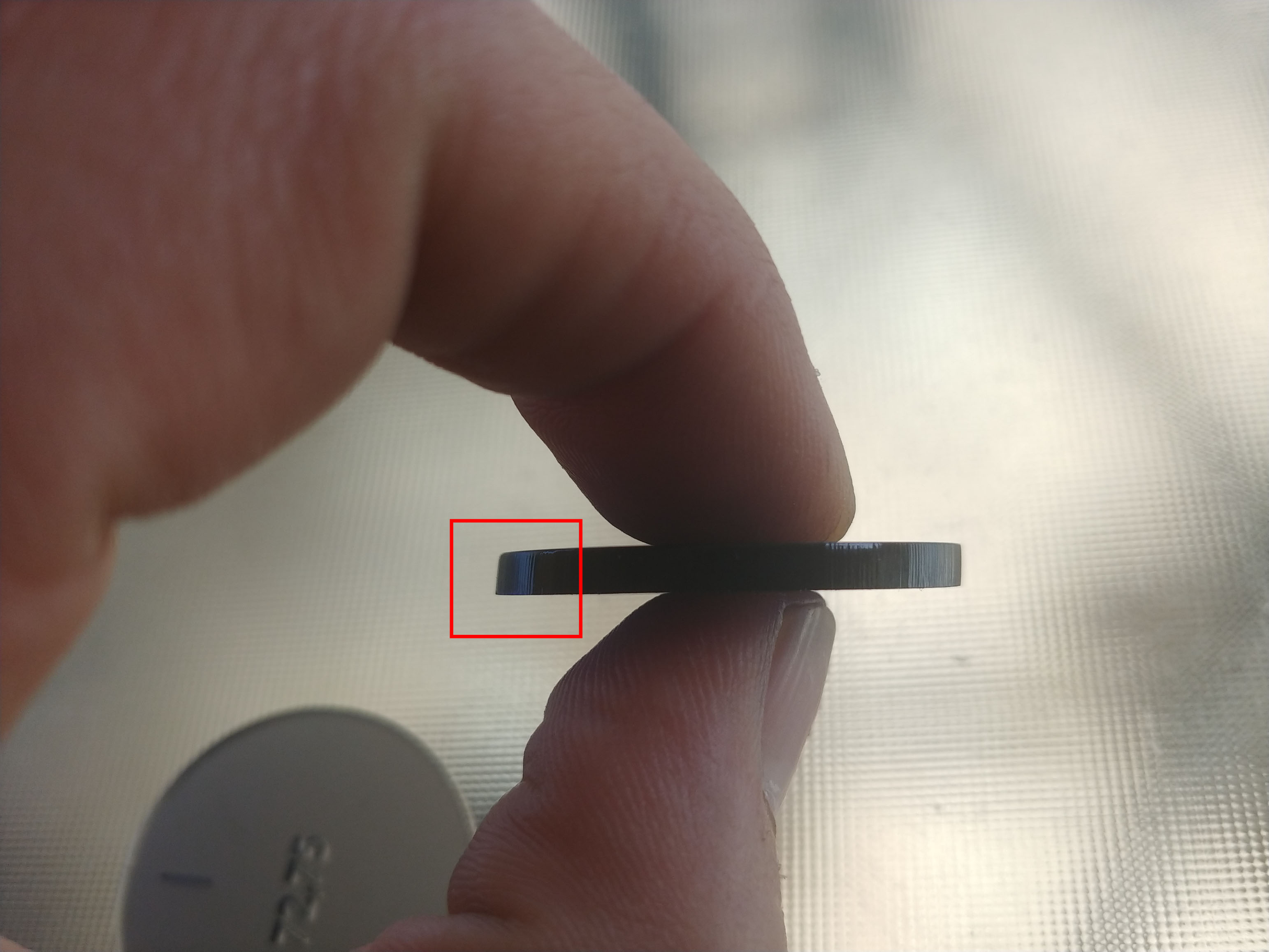
The problem is the following. The path is almost perfect, sufficient in any case, but when cutting 3 mm methacrylate, the oblique cut on the piece is unequal. This is seen when I cut a circle. In the red area of the photo the cut is oblique to the outside. In the green zone it is obliquely interior (not as exaggerated as in the red zone) and in the other zones the cut is almost perpendicular.
The machine is leveled with a maximum error of 0.4º. The x-axis, the table, everything is leveled in the same way. The x-axis belt has the proper tension, I think. I have also been testing different focal points, with a difference of 7 mm in height. I don’t know what else to check.
Can someone give me some idea what else can I check?
Could the table be tilted down toward the left front? If so it should be worse if you cut the circle in the lower right?
You said the table is level. What is important is that the table is the same distance from the objective lense on the head everywhere in the cutting area.
Is the head assy tilting as it moves. Does this phenomena occur at all locations of the table
Is the beam exiting the objective lense perpendicular to the table. Tape a target to the table, pulse, lower the table, pulse. Does the second dot move relative to the first? If so the beam is exiting the head at an angle to the table.
Many thanks donkjr. I have learned a lot. Unfortunately none of your suggestions has solved the problem.
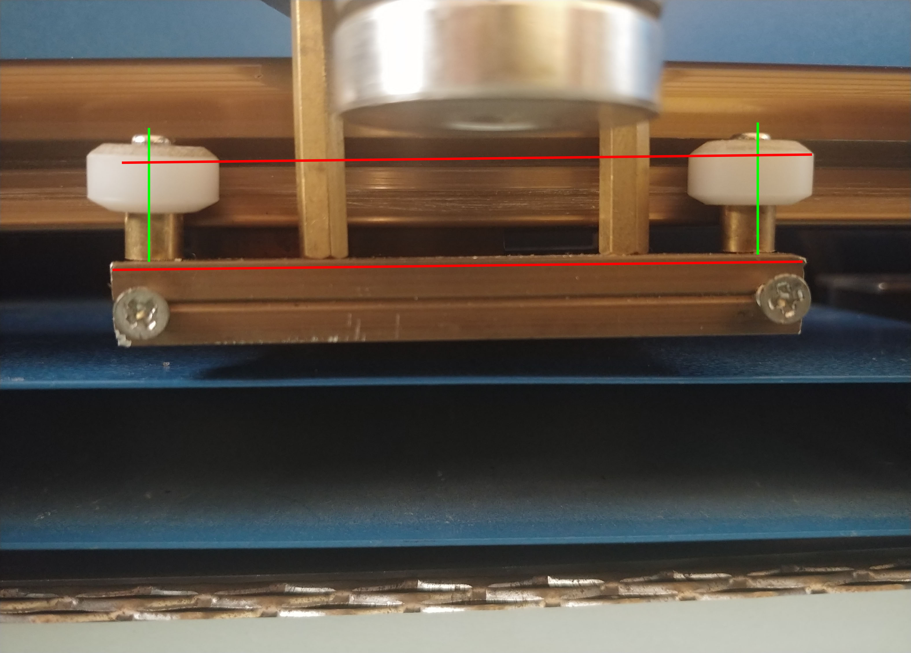
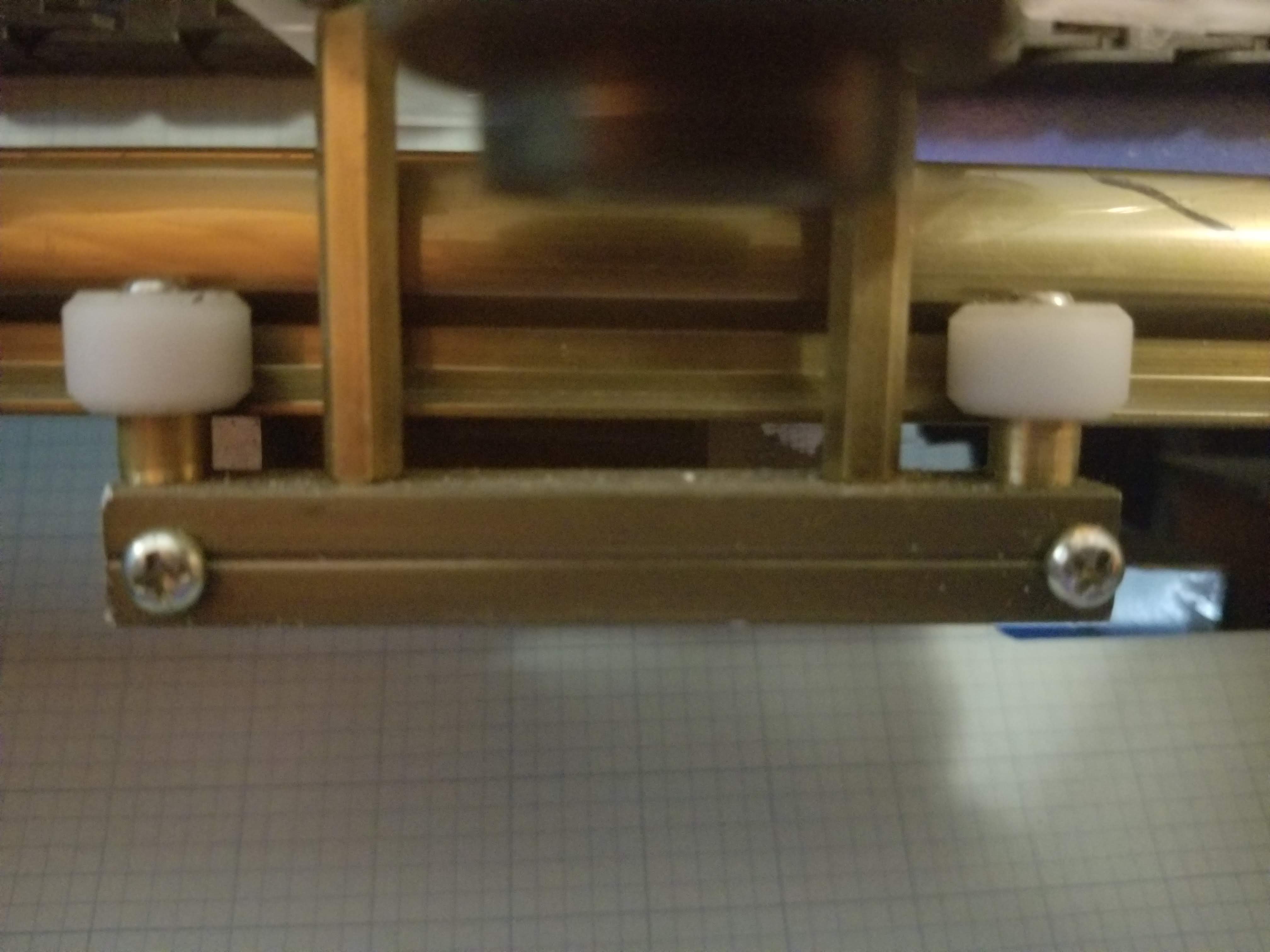
There is an item that looks suspicious. The lower left bearing of the x axis. It appears that the hole in the aluminum part is slightly larger than it should be and this causes the part supporting the bearing to be slightly tilted. Very little but inclined. I don’t know how to fix it to check if this is the problem. I guess I buy a new part.
Yes, unless it’s the camera angle, the heads left bearing looks like it is not properly up in the track and the shaft holding the roller is not at 90 deg to the gantry.
The standoff holding the lower bar also looks canted. Looking at it I wonder if the entire head assy is in the track properly?
Did you test the perpendicularity by raising and lowering the table after pulsing a dot.That should show you if the head is at an angle to the bed?
Did you test to see if this problem occurs at other locations on the cutting area?
It seems to me that the hole being oversized would not cause the wheel mount to be canted. It could change its position to the left or right. When you tighten the mounting screw the bottom of the spacer should locate against the bottom bracket and it should tighten up perpendicular. That is unless the bottom of the spacer is not machined square to its mounting hole.
Yes yes, I tried all your proposals and in all cases the result was correct. The problem recurs throughout the entire work area in exactly the same way.
Speaking of x-axis bearings, I squeeze the lower left bearing the same as the others but I only have the problem in this hole. Could you explain a little more your method to tighten the bearings please?
My point on the bearing mounting is that if the spacers end is machined at 90 deg to its hole when you tighten it down it should end up perpendicular to its mounting surface.
I am wondering why the perpendicularity test passes and the cut is still at an angle. It should show any error from the heads alignment??
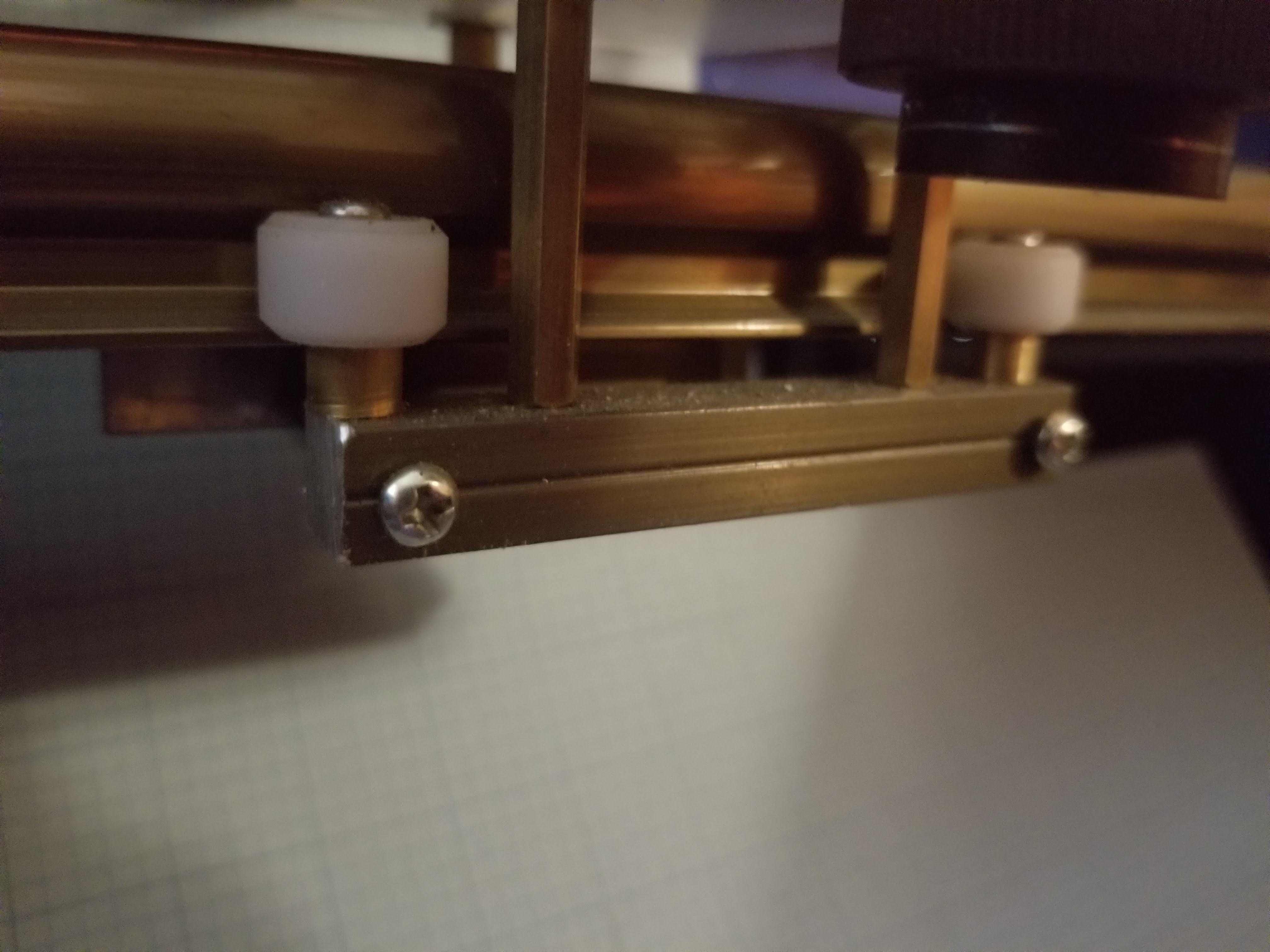
Attached are pictures of my head assy. Unless we are being fooled by the camera angle this assy looks straighter and seated in the track better than yours…
Strange: If the your head is canted why does the test not show it???
Ignoring why the test does not show the error:
Is it possible that the two large mounting spacers to the right of the left bearing and to the left of the right bearing (not the bearing spacers), are two different lengths? This would cant the assy as they are pulled tight?
Note: on mine there is some small upward play on the head assy. How about yours?
Excuse me I have spent a few hours trying to solve the perpendicularity of the bearing but I could not.
The perpendicularity test does not fail because what changes between the two shots is the height of the bed. If the x axis doesn’t move, the shot is exact, so I think everything points to movement.
The hole in that bearing has much more slack than the others. If I squeeze the part with the bearing upside down it looks solid enough but the fact is that when all four bearings force together the lower left bearing stays in an oblique position. No matter the bearing you use, it is always in the same corner.
I’m going to look on ebay if I can get something cheap, I don’t see another solution.
The photos you have sent me have been decisive, thank you very much donkjr.
I’m not sure … these are all very accurate measurements and I don’t have that much skill and DIY tools. I’m going to keep thinking about it a bit. Yesterday I sent a message to the seller explaining what was happening to me. Let’s see if he answers. The piece to buy it comes in a kit and costs about 60-70 euros …
35-40 euros … but it does not arrive until the beginning of June and I need to start selling in the beginning of April … I re-evaluate your solution donkjr.
I’m very sorry to have left this thread. I tried to contact the seller but got no response. Then the virus came to Mallorca and has left me out for a while. In any case, we must continue forward. Yesterday I tried to contact the seller again and today I received a response from him. He asks me for an explanatory video. I’m going to start with it. Anyway I have sent a link to this thread.
donkjr, I already tried playing with the bed tilt but it didn’t work.
cprezzi, I think I have it very focused. Anyway I repeated the alignment twice and the result on the acrylic pieces was exactly the same. I think if this were the problem at least the shape of the parts should change a little after the two laser alignments.
In all cases, thank you very much guys, we keep moving
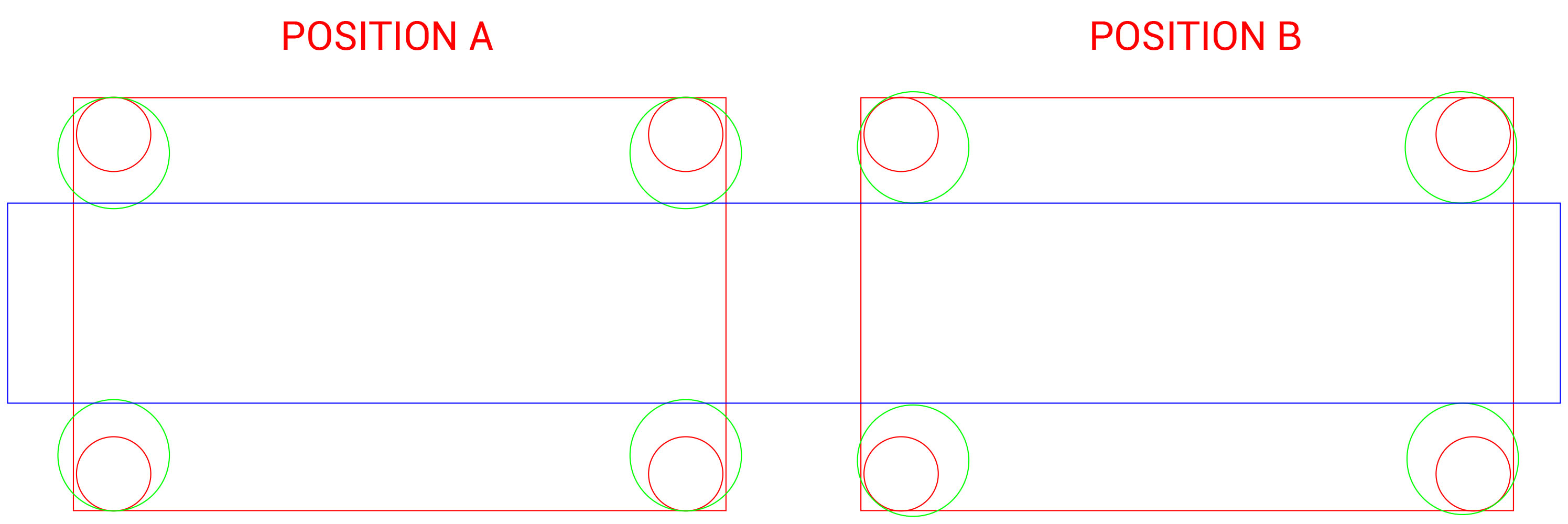
The red circles represent the pillars that are inserted in the aluminum piece. The green circles are the bearings. I think the optimal position is A but I’m not entirely sure.