Good afternoon, new to this board, Cohesion3D oriented me here ! Looks like a good place to add to my usual forums !
OK, so here is my situation.
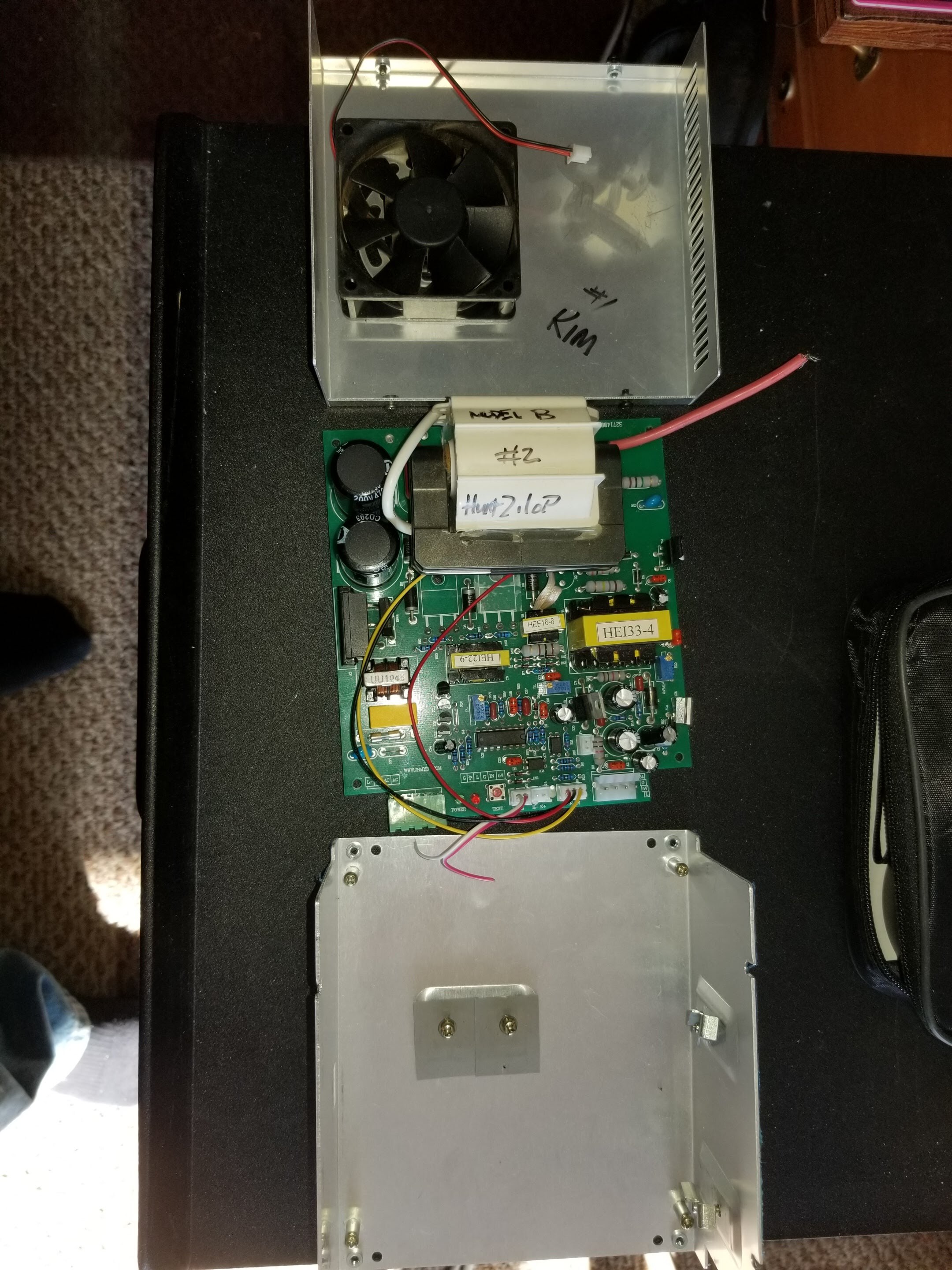
I have 2 K40s, both were working well. I have a Z-table on K40 #1 with a C3d mini board and have been using it with Lightburn since lightburn was created. It’s going very well.
My second K40 (let’s call him #2) was working fine with the original board. I finally decided to add a z-table to this one too and so decided to also finally pop in my C3D Mini board in it to have two identical machines. Did all the connections, alignments, etc and everything was going pretty well. It’s a lot easier with an identical machine next to it to follow setups !
All the time I was doing my mirror alignment, I was using the TEST button on the control board, it worked well. I was using lightburn to move the laser head to where I need it to be for alignment… which was also working quite well. I’m able to control X-Y and Z axis with Lightburn… but I can’t get lightburn to fire the laser.
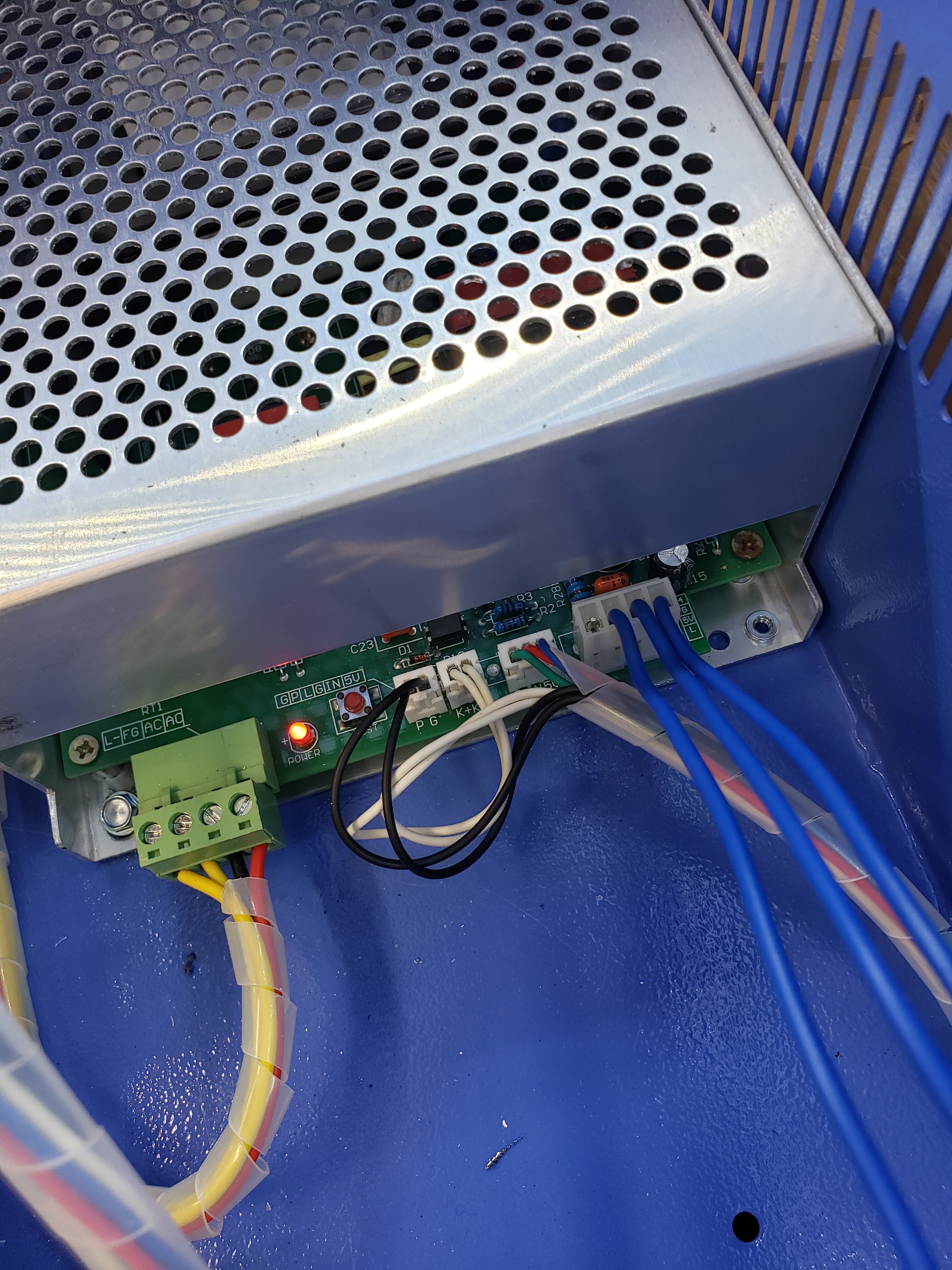
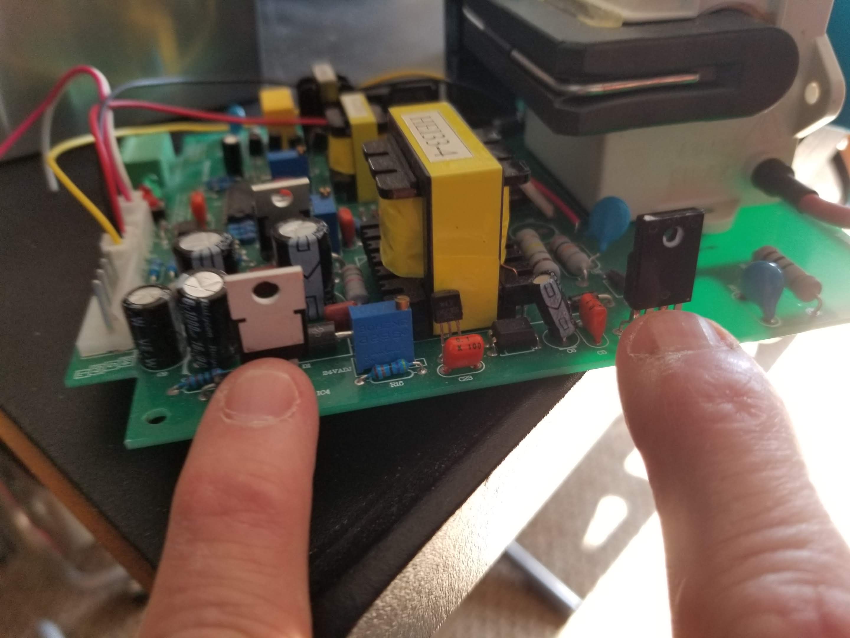
After doing a bunch of tests with Starla from C3D, we came to the conclusion that it’s not a board problem but seems to come from a problem in the PSU. When I put a jumper between the L and G pins I don’t get any fire. When I push the TEST button on the control panel, it fires. When I push the small TEST button on the PSU itself, it fires.
I have just received a new Cloudray PSU, but don’t want to swap it before I’m absolutely certain that there’s nothing that can be done with the old PSU. I checked the fuse and it’s fine. I checked the cables and I have good continuity on both ends of them. We even tried putting a jumper directly on the L & G pins (on the PSU) and there is no fire at all…
Help please, I don’t have an electronics background but I’m pretty handy… and I don’t have electronics tools either.
It is a very weird situation that you have. How it can pulse from the control panel test button, but not when L and G are shorted is a real head scratcher. I am sure that Don, our resident LPSU expert for the K40 will be able to walk you through some troubleshooting to figure this out once and for all.
My c3d board is connected using the three blue wires (G, 5v and L).
The two black wires go to my test button on the control panel. That test button works. When I put a jumper between the G and L pins on the PSU (blue wires), nothing happens.
I tried on my Machine #1 using the same jumper, and it triggers a fire. I checked my blue wires carefully with ohmmeter for conductivity and it’s all good.
You are saying that you jumpered the supply in machine #1, You are NOT saying that you tried machines #2 supply in machine #1 right?
When you jumpered the pins L and G on the right connector (blue wires) did you do it with the connector plugged in?
If yes then unplug the connector and ground L without the connector plugged in.
Question 1. Correct, I didn’t swap the PSUs. I just did the same test on both. When putting jumper between G&L, Machine #1 fires, machine #2 doesn’t.
Question 2. I did both tests. With the connector plugged in (jumper on other end of cables) and with the connector unplugged completely, putting the jumper very carefully on L&G pins directly. This ruled out a problem with the blue cables and connectors.
It seems to be a very similar problem, at least the symptoms are the same. But my understanding of @WoodenCreationz is that he has an external DC PowerSupply providing the DC current to his main PSU… which I don’t. I have good ground all over the place, sanded the paint behind, inside, under the machine and tested for continuity everywhere. It seems fine to me.
For the record. My C3d board is now disconnected completely (power side), as we determined that the problem was on the PSU side. If I can get the laser to fire when putting a jumper cable between L and G, then I’ll replug my C3d board. The board was making the X-Y and Z axis work perfectly, on jobs and on toggle. Problem is just no fire when we sent the command to the PSU, which apparently really only grounds the L pin.
Looking at this weird problem let me first summarize where we are:
These things fire the laser.
The Test button on the control panel
The test button down on the supply
These things do not fire the laser:
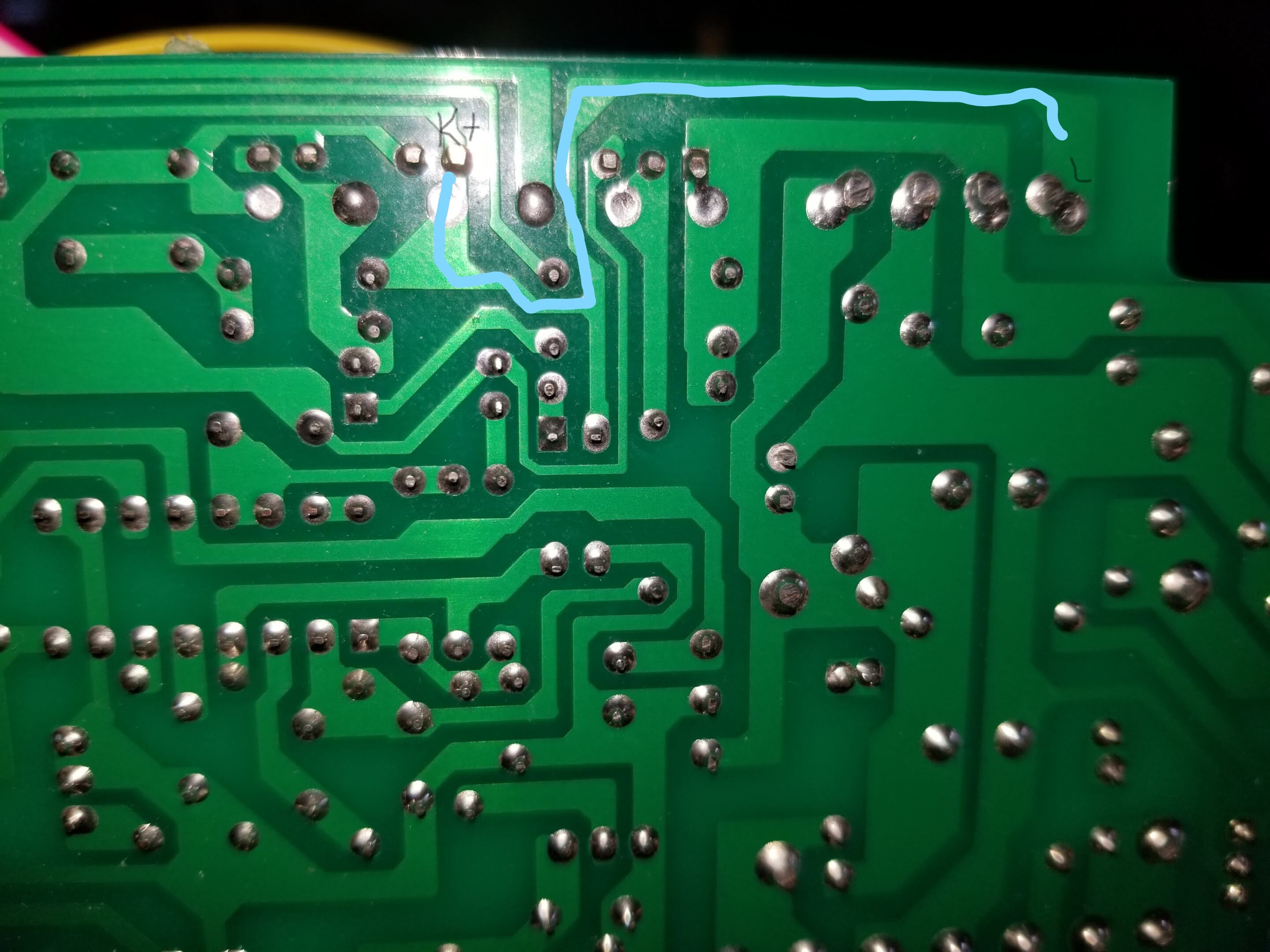
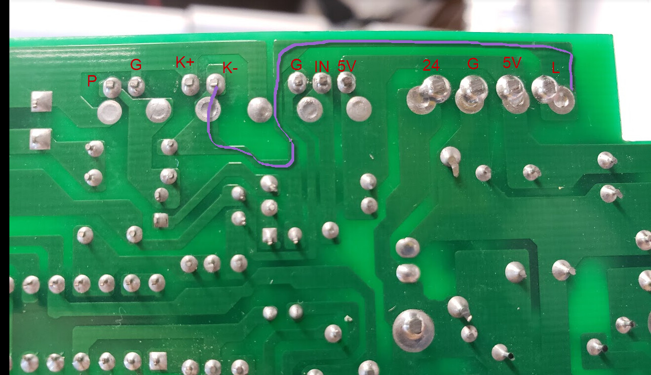
The software driving pin L (on the rightmost connector)
Grounding pin L (the L on the right-hand connector) with its plug removed
Let me know if the above is in any way wrong.
The fact that grounding the L pin (without a connector) does not fire the laser but the test switch across P-G does, leads me to suspect something awry inside the LPS.
From here on out when doing these tests keep the top and back covers closed.
A stab in the dark test:
With power off at the LPS:
Remove the 5V-IN-G connector
Put a jumper between 5V and the IN pin.
Remove the rightmost connector
Power the machine back on
Ground the L pin
Does the laser fire…???
If the laser fires then let us know…
If not let’s make some measurements:
Measure and list the readings from the following:
Continuity measurements (with the DVM on ohms, machine power is OFF, all LPS connectors unplugged)
From the G pin on the rightmost connector to every other G pin
Moving right to left"
The G-IN-5V connector =
The P-G connector =
The FG connector =
Voltage measurements: (with DVM on volts, Machine power on, all LPS connectors plugged in)
L =
5V =
IN =
K+=
K- =