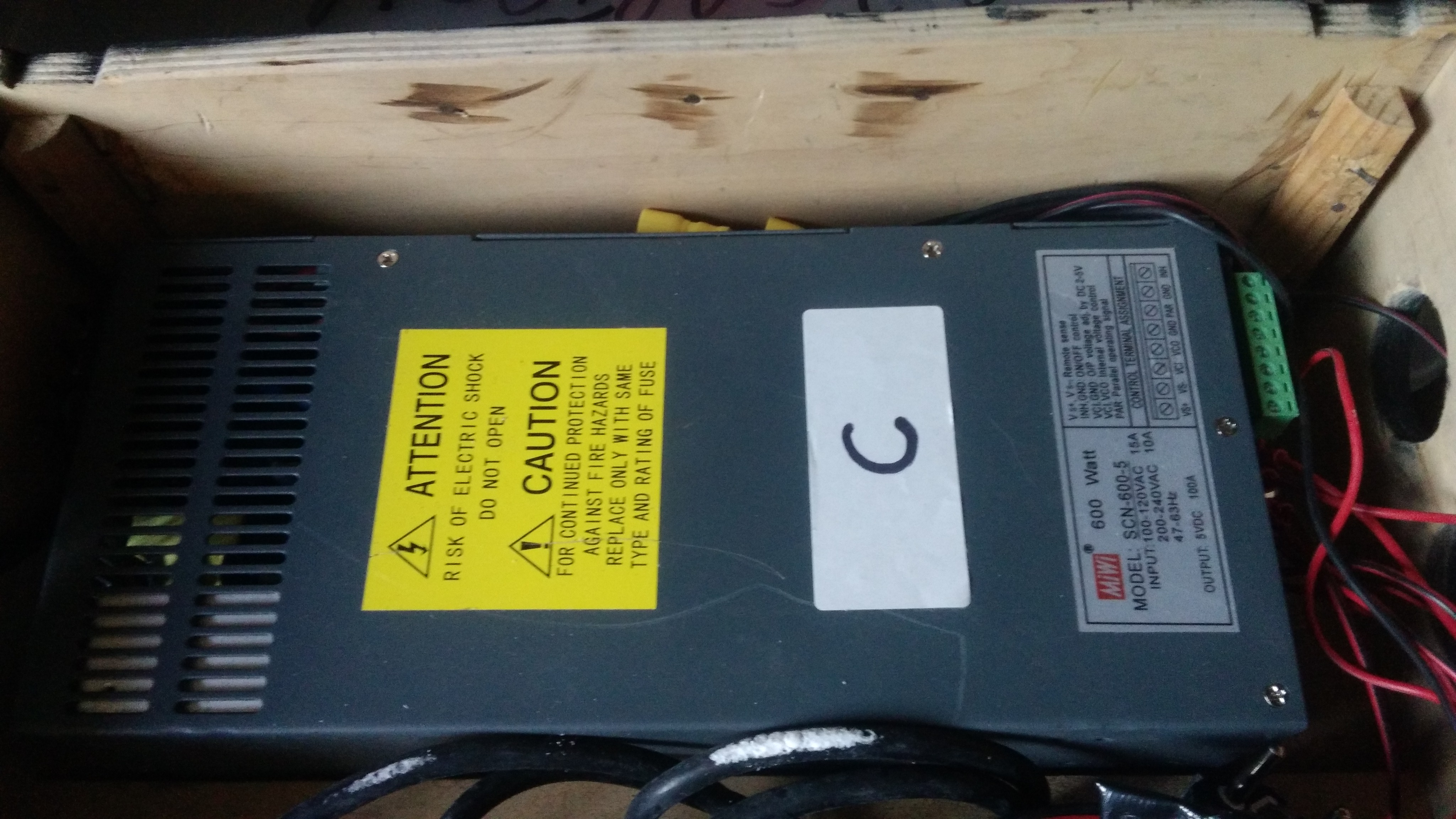
Hello, I’m starting with one meter / 60 leds WS2812 ledstrip + ATtiny 85 and that works fine with FastLED. However I wonder why all my leds are turning to yellow/red (not only the far end) when the potentiometer is turned to max … since I’m using a big power supply as you see in the pictures (+5V 100A !). Any help would be appreciated.
measure the voltage when they are all yellow/red. I suspect it may be well below 5 v at that moment. you may have a short somewhere dropping the voltage more that you would want.
you seem to have the ground for your stip connected to the hot rail. (at least that is what your drawing shows). Move that to the ground and see what happens.
missing/deleted image from Google+
I would connect the strips (+) and (-) power directly to your PSU not through breadboard and/or that potentiometer board.
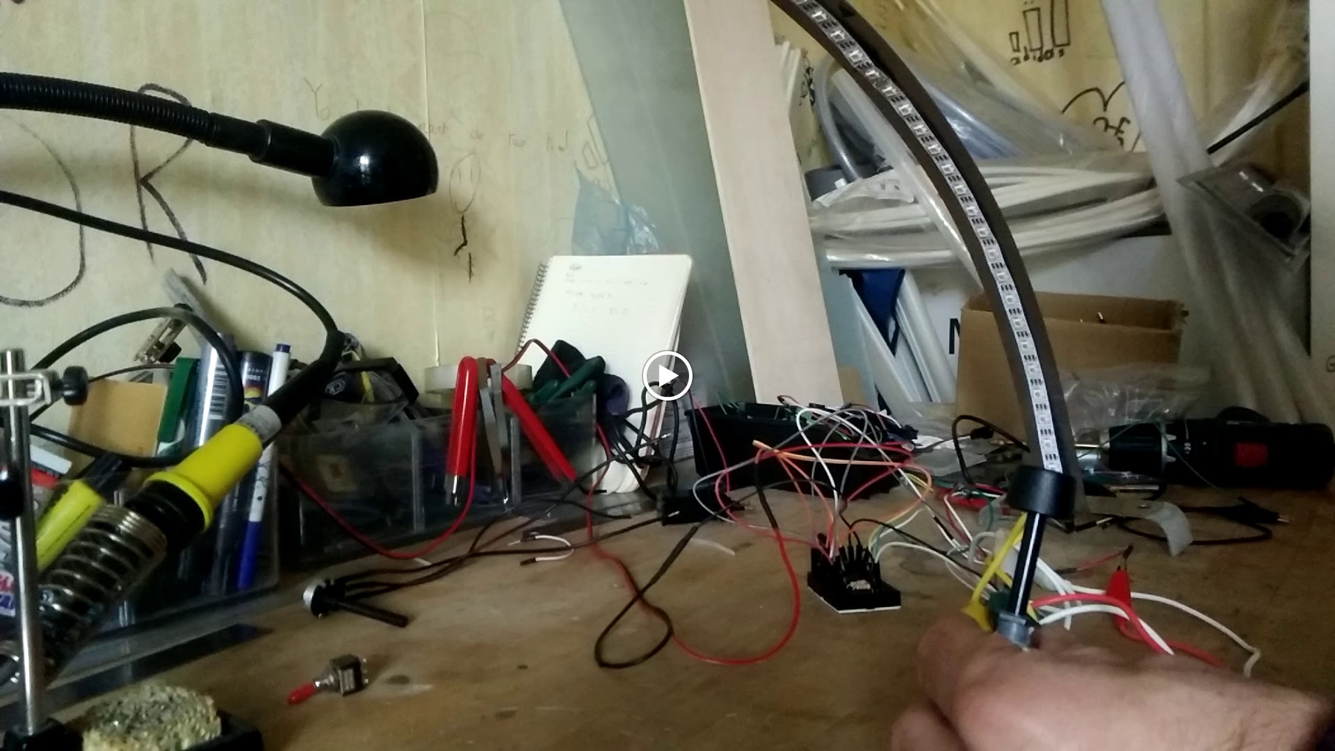
I think analog potentiometer has something to do with Attiny digital pin. I can see in the video when you turn the pot to its max strip goes yellow.
@Derrick_Giscloux Indeed it happens when the potentiom. is full open then I get around 2.5V at each yellow/red pix and the brightness seems at its maximum. Below that everything goes to 5V with a normal white and things slightly dither near to shutting down + the potentiom. has a on/off switch @Mark_Estes you found a error in Fritzing thx  @JP_Roy I can’t bypass the breadboard at this point.
A potentiometer on the Vin pin of the LED’s? Do NOT do that. Vin should be directly connected to the 5V power source.
The only thing that the middle pin of the potentiometer should be connected to is an analog input on the ATTINY.
These are digital strips, and all the brightness and colours are digitally controlled via the Din pin.
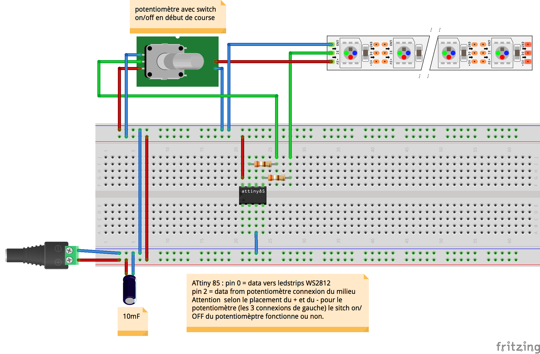
@Andrew_Tuline Yes of course Andrew thx for the advice, indeed I corrected this: power supply directly connected to ledstrip +5V and the middle pin goes to Attiny digital pin. But the potentiometer has 2 additional pins that cut the signal : there is a “clic” at the beginning of the track. So I’ve connected +5V power supply to this in order to use it as a on/off switch for the entire system. Please see diagrm. attached. Unfortunately I still get that yellow/pink colour at full potentiom. I can’t see where is the problem. Here is my code, really simple:
#include <FastLED.h>
#define NUM_LEDS 63
#define DATA_PIN 0
#define pot 7//potentiometer pin analog. Attiny
int brightness = 250;
// Define the array of leds
CRGB leds[NUM_LEDS];
void setup() {
//delay(3000); // in case we do something stupid. We dont want to get locked out.
FastLED.addLeds<WS2812,DATA_PIN,RGB>(leds,NUM_LEDS);

pinMode (pot, INPUT);
}
void loop() {
brightness =map(analogRead(pot), 0, 1023, 0, 255);
// First, clear the existing led values
FastLED.clear();
for(int i = 0; i < NUM_LEDS; i++) {
leds[i] = CRGB::White;
//CRGB(0, 0, 255);}
  //luminosité potentiometrer
   FastLED.setBrightness(brightness);

	// Show the leds
	FastLED.show();

	// Wait a little bit before we loop around and do it again
	FastLED.delay(10);
}
}
missing/deleted image from Google+
Your code and wiring now look fine and ran perfectly on my 40 LED test APA102 strip without potentiometer and swapped ATTINY for a Nano.
On line 16, try changing ‘RGB’ to ‘GRB’ or some other colour order and see what that does.
You may also want to try removing the two resistors on your breadboard. I never use them.
Also, add:
Serial.println(brightness); // right after you read the pot value.
and monitor to find out how that’s working for you.
Finally, you may need to change colour correction by appending something like this to the end of your addLEDS definition:
.setCorrection(0xffb0e0); // muck around with this value.
This is called grasping at straws.
@Andrew_Tuline I did all you mention but I still get the yellow/red color all along the strip (ok lets say orange). I can’t experiment the same thing with a very shorter strip so I really thing it has something to do with the potentiometer. When it is turned to its maximum I get a voltage drop at the end of the strand : 2,5 volts . Okay of course a potentiometer is a variable resistor but how then do I deal with it? Is it a issue because Attiny has no dedicated Analog IO or something …?
If you think it’s something to do with the potentiometer, then hard code the potentiometer brightness value and find out.
Since you did everything I said, you should know what the min and max values from your Serial.println statement and they should correlate to what you’re expecting.
The thing is with all this stuff is to make sure you KNOW what values you’re getting and you can do that with Serial.println statements. I write little test programs to make sure I understand all this before incorporating that functionality into FastLED programs.
I don’t use ATTINY’s, however I’d be looking at the pinout and making sure that you’re connecting the middle pin of the potentiometer to an analog input of your ATTINY and defining it correctly in your code.
From the looks of it, pin 2 is A3, pin 3 is A2 and pin 7 is A1.
In addition, I assume you’re removed that resistor between pin 7 of your ATTINY and the potentiometer.
you could read the switch and use that to set the brightness to 0 rather than trying to use it as an on off switch for the power line.