I kind of hoped it was one of the tubes being loose and just needing one of the many fittings tightened, but as one might reasonably guess, it’s the radiator.
It really sucks water through when it’s running, but leaks only a little bit when it isn’t.
I’m running it intermittently while doing some light cuts, to try to keep enough water in it.
I now understand that it is massive overkill for this spindle, so for the moment instead of repairing it I think I’ll look at @Eclsnowman’s approach and use a CPU cooler instead.
Or I might use K-Seal. I wouldn’t run that stuff through the pump or spindle, but I could remove the radiator block, fill it up with K-Seal, cap it, and let it sit for a few days. Maybe put it in the oven at 200° for a while too (obviously not tightly capped! ) in order to make sure it seals. Then pour it out, rinse it out well, and put it back into service.
The water is being blown through the fan, so it seems like there must be a leak inside the box. The solder joints between the straight and U sections all seem dry. I haven’t removed the radiator yet; just finished draining the unit.
Glad I’m using distilled water (with just a little algaecide, same as if this were cooling a laser) because it won’t conduct electricity well.
It doesn’t appear to be at any of the joints; I felt them and they were dry while I watched water spit out the back of the fan. I think the leak is inside the radiator.
Trying to solder inside the area with the fins? Well, I’d say that soldering a literal heat sink takes skills I don’t have.
If the adhesives do not work I would try to solder using a map torch with soldering tip on it and plenty of flux.
I don’t think silver solder is necessary as this is low pressure system.
So it does seem unlikely that the leak is actually inside the tubes that go through the radiator fins. Before I try to find the leak in the radiator, I’ve bypassed it. I’m filtering all the water I drained from it through a coffee filter as it goes back into the tank to make sure I don’t damage anything, and then I’ll try running it with a closed loop (not connected to the spindle) and see whether it leaks without the radiator in place.
That way I won’t waste time trying to repair a radiator that isn’t actually leaking; or in the alternative will know that it’s the problem and can focus on fixing it, or calling it enough and moving on.
I’ve run it with the radiator removed now for a while any nary a drop spilled. Gotta be the radiator.
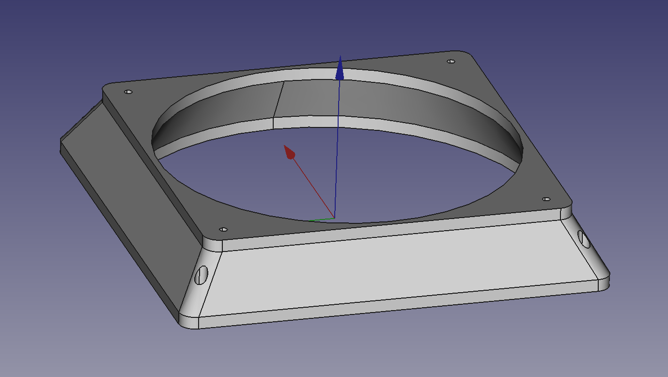
I think it would be easy to 3D print an adapter for the existing 6 inch / 150mm fan to this slightly smaller radiator. That’s cheaper than $80+ for a CPU chiller and keeps the flow and temperature alarms in circuit. And easier than repairing the probably-junk radiator shipped with the (knock-off) unit.
The problem is fitting around everything else in there, including particularly the flow sensor right above the radiator. And the 6" fan isn’t going to pull a lot more air through the 2:1 rectangular radiator anyway. I barely need a radiator at all, so this will be plenty. Didn’t see any reason to pay $25 for a radiator that I’d have trouble fitting and wouldn’t necessarily give me meaningfully more cooling that I don’t need.
If I were doing this from scratch I would have bought a 120x240 radiator with two fans on it which would have given me some cooling redundancy, but that’s about $80 plus another power supply, so $100. $16.99 plus a couple dollars of PETG or PLA+ sounds better to me.
Once I get the new radiator that I ordered, I’ll measure all the hole sizes and pitches. I have this parametric design so all I’ll need to do is plug new numbers into a spreadsheet and this will be ready to print. Probably in PETG because it’s so dimensionally stable and easy to print.
The radiator is rectangular with screw tabs in the corners. Adapted the top to pull air through more of the radiator (substantially all, I think). Made counter-sunk holes for screws to mount it to the fan. That should be easier than the fastened-from-the-back approach that was originally on it.
The holes in the fan housing were I think intended to be M4 clearance holes. I tapped them M5; while the holes were larger than standard for M5 they were small enough for M5 screws to hold. I enlarged the fan mounting holes to 5.5mm for clearance; I can always drill them out a bit more if necessary, but I think this will work.
Also, I measured, and there isn’t really clearance for a 240mm radiator thanks to the flow detector.
I don’t think this radiator actually runs fluid through the fins. I think it’s just a set of “heat pipes” that terminate in the water flow. I definitely wouldn’t use this for a laser (despite the meretricious product labeling) but there’s a lot more leeway for temperature for a spindle than a laser.
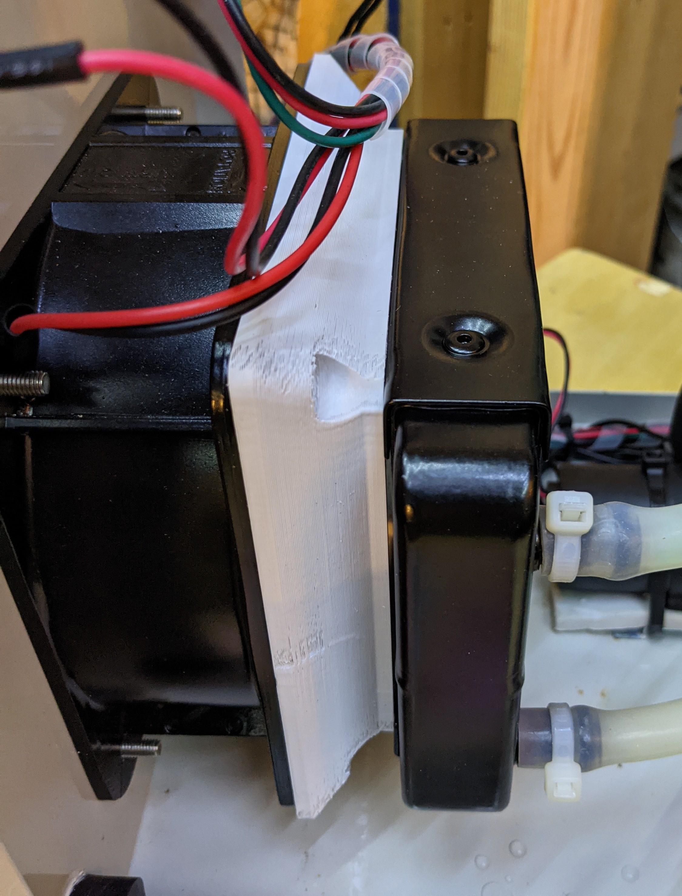
Printing this in PLA+ was a mistake; I did it because I planned to tap the holes. I haven’t tuned the printer in its current state for PLA and the output was a little messy. Way too much retraction, for one thing. Probably don’t need any.
However, on closer inspection the holes in the radiator are all tapped, so I needed to drill them out through and the countersink them. I did that on the prototype. Also, it should be a few mm deeper based on the screws that came with this radiator, so I did that too. No more reason to print PLA+, back to PETG for me!
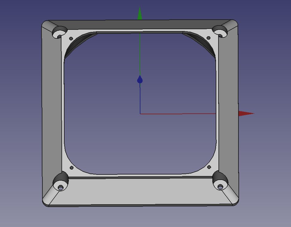
Here’s the underside as currently modeled with the screw holes coming through.
Haven’t yet printed this latest model (might stick with the prototype as good enough), but I updated the repository with what I made.
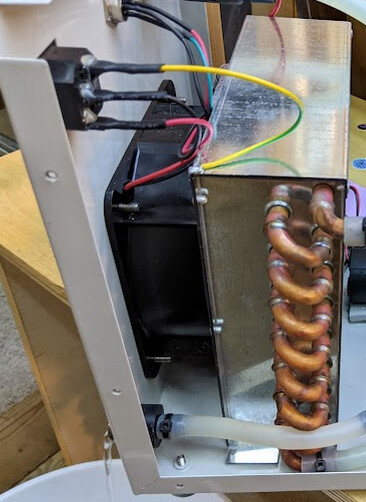
And… there’s also a little leakage on the outside coming from the exit from the flow sensor. Don’t know why yet. Will re-seal that and try again later. But water and air flow through this radiator fine.
Here you can see the underextrusion from excessive retraction (which of course put blobs elsewhere) as currently installed.
I unscrewed the leaking outlet and found that it had been sealed with liquid pipe seal, including the two separate gaskets at the base. I tried three times to seal it with pipe tape, and was not successful. For the last try, I put silicone at the base, and against both sides of the two gaskets, and all around the threads. Now I’m waiting a few days for it to cure before I fire up the unit again and hope that this time I got it to seal right.
I had mixed results in sealing pipe threads with Teflon tape and other sealants until my brother showed me this stuff.
Never had a joint leak since with this:
Thanks @donkjr! That’s probably something like what was in there before, though probably higher quality. It felt like a silicone compound with a lot of filler, stiff almost like silicone caulk. I had to cut it out of the threads with a knife and it was a bit stretchy.
I felt a little silly reading your recommendation immediately after using silicone sealant. I was worried that I had messed these connectors up for good. Thankfully, my silicone sealant expedient appears to have worked. No drips for a quarter of an hour or so is probably good enough.
I’ll keep the advice in mind for the future that this stuff works well!
Looks like it maintains about 1.5-2°C above ambient with extended free running (about an hour and a half). I’d expect it to be fine even if it were 20° above ambient. I’ll find out how much that changes under load soon enough.
Edit: I think it’s better than that. I turned off the spindle and left the unit running for almost another hour, and it dropped about .5° or less (the measurement is noisy).
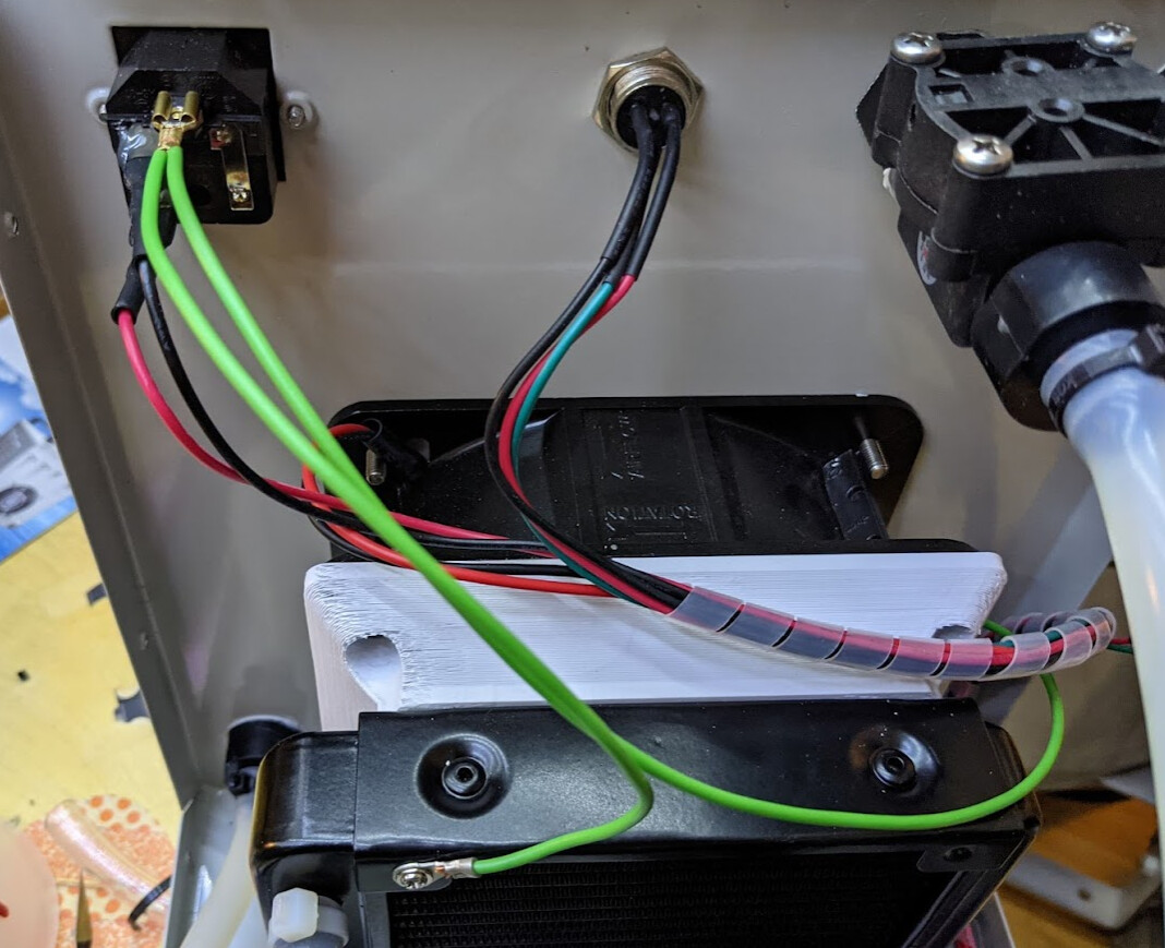
In my new configuration, the radiator is isolated from ground, so it’s not a good way to ground the unit. (I’m not sure the old way was a great way to ground the unit, but it was probably good enough?)
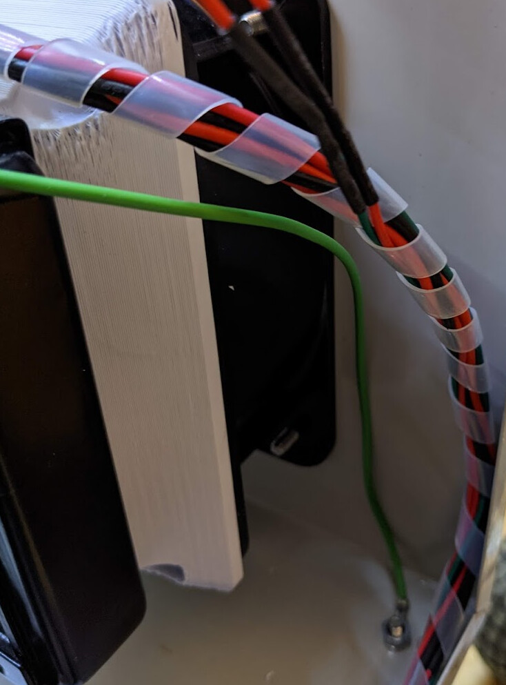
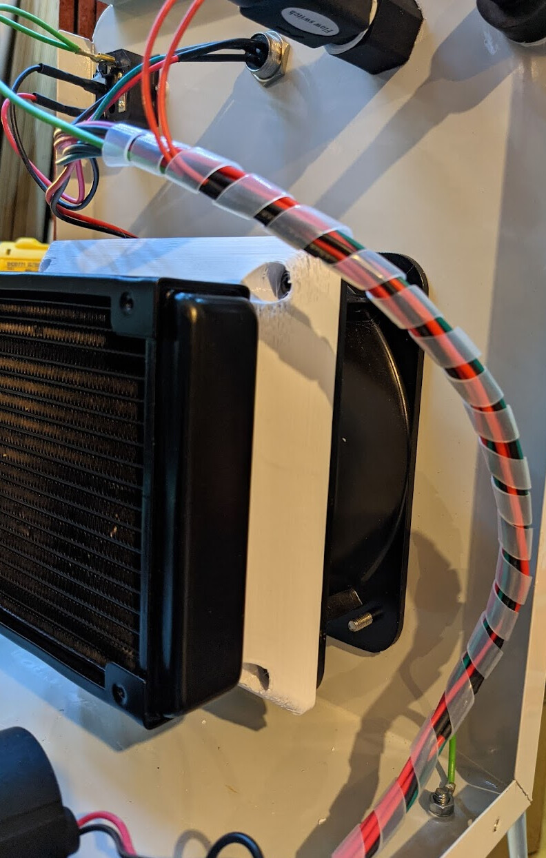
I made a harness to ground both the radiator and the case. I used a short M3 screw that came with the radiator to attach the ground wire to the radiator:
Then I unwrapped the spiral wire loom all the way down near the foot and wrapped it up incorporating the ground wire to keep it from chafing against anything:
 ) in order to make sure it seals. Then pour it out, rinse it out well, and put it back into service.