@cprezzi Is not using a POT an option?
Yes. You could just bridge the center (input power level) to the right (5V) pin to fix power to max. Or better use a fixed voltage divider to set the max. allowed current. But I don’t recomend both.
Grbl has only 256 PWM steps from 0 to 100%. If you just need 10% power for the darkest part of an engrave, then there are only 25 different power levels left. That’s not enough for grayscale.
1 Like
Ciao @cprezzi sto cercando di collegare CNC shield al PSU del K40. La cnc shield è alimentata da un alimentatore aggiuntivo. Non riesco a capire cosa sbaglio, il pwm non funziona. Per favore potresti aiutarmi?

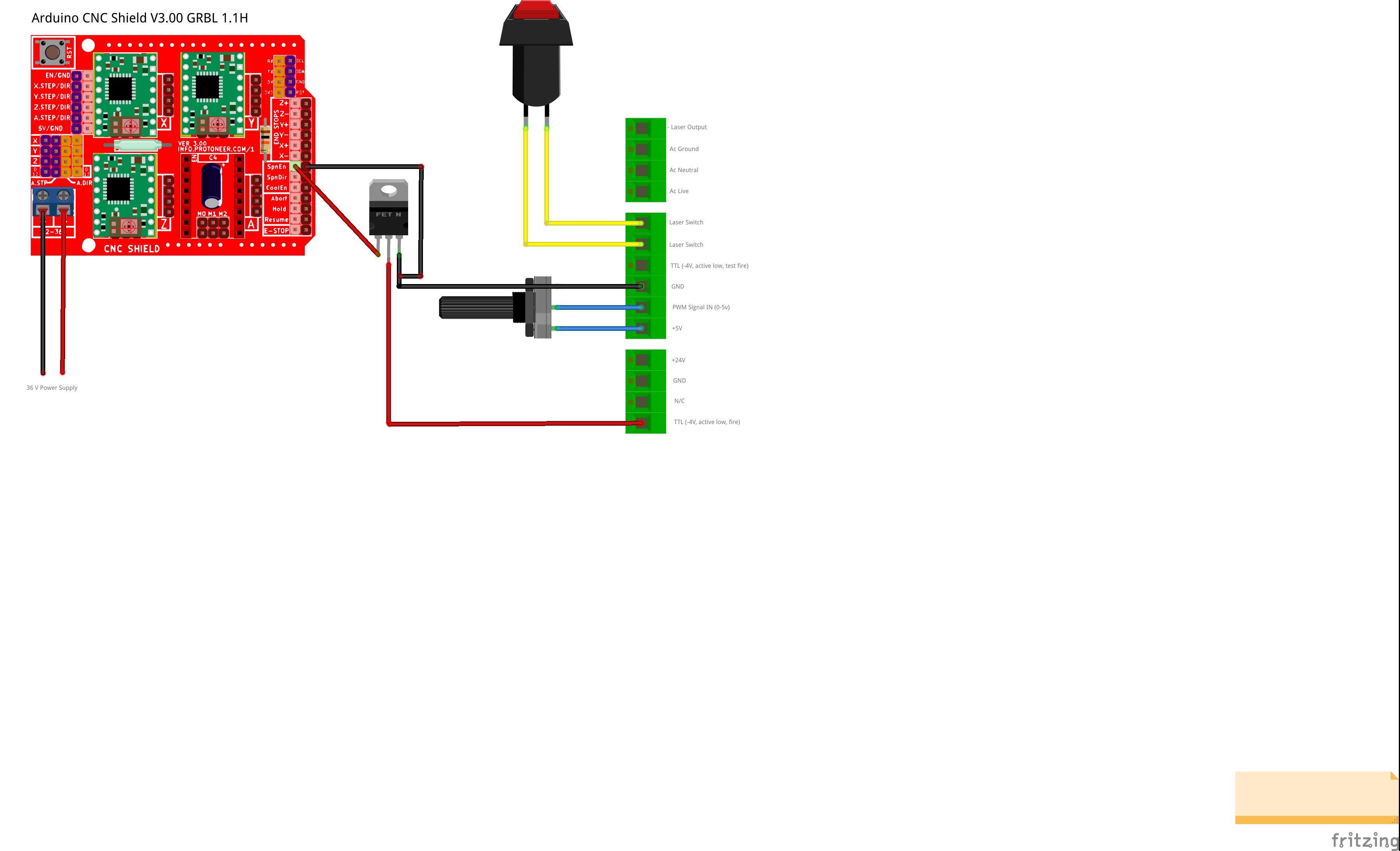
I’m sorry, my italien is very bad. I would suggest to leave the potentiometer of the K40 connected to GND, IN and 5V of the PSU (to set the maximum power) and use the TTL (active low) pin for the PWM signal of the CNC shield (usually on SpnEn).
A small problem is, that the PSU needs an inverted signal on the TTL pin. So you need to invert the PWM signal of the CNC shield. This could be done with a NPN-Transistor or N-Channel MOSFET:
https://www.quora.com/How-is-MOSFET-used-as-an-inverter
For this to work, the GNDs of the CNC Shield and PSU needs to be connected too.
Hi @cprezzi, Thanks for your suggestions. Sorry for my English 
I modified my scheme by inserting an N-Channel Mosfet and the potentiometer. Is it correct now? I forgot to say that I am using Grbl 1.1F, so using SpnEn Pin is the greyscale preserved (or i need to use Z+ pin)?
1 Like
That scheme looks fine.
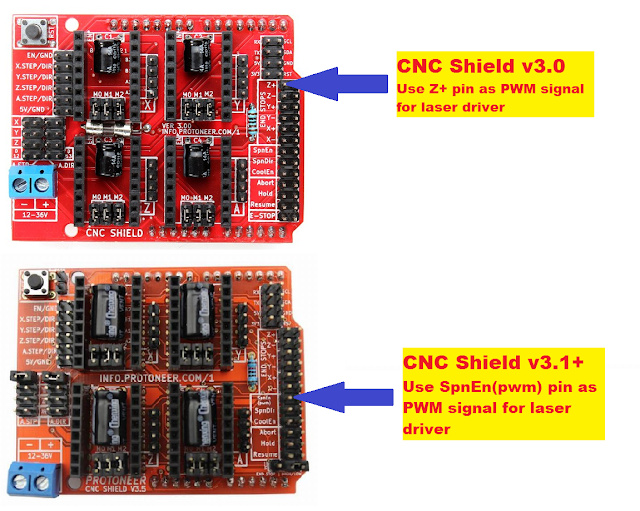
If your CNC Shield is the older version V3.0, you need to use Z+ insted of SpnEn.
On CNC Shield V3.1 the pins was swapped, so you could use SpnEn(pwm) pin.
Hi @cprezzi, thank you very much. Do you recommend using a 1k ohm resistance between Z+ and mosfet? Also, I am unable to find a p75nf75 mosfet, is there an alternative?
Yes, I would add a 1kOhm resistor to protect the Arduino output. Eventually it’s also wise to connect a 10-100kOhm resistor between gate and source of the mosfet, so it safely stays off when the Arduino pin is floaring.
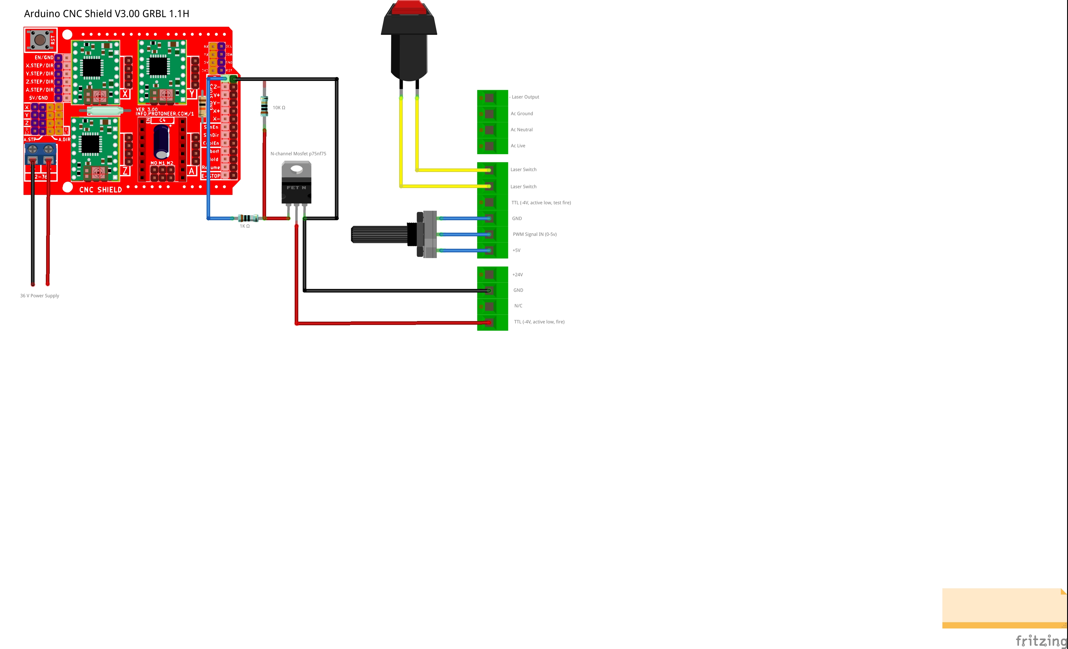
This looks just fine and should work as expected.
For the mosfet you can use many types. It just has to be N-Channel and accept TTL level at the gate, like IRL540 or IRLZ44.
1 Like
Hello
some indications on the characteristics of laser power supplies make me doubt:
the response time of the power supply to a TTL signal (L inputs) is close to 1ms, which suggests that the PWM injected on one of the TTL inputs should be <= 1Khz than it is really for the output of the arduino and the precision obtained in the end?
Still on the subject of PWM: this time at the IN input because it is indeed this input that we recommend to use
the PWM must have a frequency> = 20KHz (dixit characteristics of several Laser power supplies)
it is not possible to have such a frequency with an Arduino while maintaining a pwm variation of 100% in 256 steps
this is why I migrated to the port of GRBL11f on a BluePill STM32 card which works internally at 72MHz and allows me to have 20KHz in 256 steps 0-100% PWM and therefore to attack the power supply as it does is provided by the IN input
Nb: you need> = 20KHz because in the power supply following the input there is a low pass filter which blocks everything> 20KHz and transforms it into a continuous 0…5v signal proportional to the PWM with a correct residual ripple rate
if it is <20Khz, the residual ripple may cause fluctuations in the power of the beam
adding a filter at a lower frequency before the IN input would be detrimental to the laser response time
I am in the realization of the electronic card and I would like to have your opinion on these questions
Best regards
hello, being a complete novice i’d like to also control my k40 through a esp32 grbl board that have a 0-5v PWM. What wattage should the resistors be in the diagram above? (or it doesnt matter?) thanks
The resistor wattage doesn’t realy matter,as these are just pullup/pulldown resistors. Usualy 1/4 W is ok.
2 Likes
Just ordered the parts. To make sure I am wiring this properly: Board’s PWM to L and Board’s GND to GND?
1 Like
I just finished the wiring with an IRLZ44. My output seems to be between -0.26v and 0.26v.
M3S0 to 5= From 0.26V to 0V
M3S5 to 1000= 0V to -0.26V
So, technically it triggers my laser (yay!!) but I’m worried that I won’t be able to do picture engraving down the road if i cant go lower than -0.26V
Am I missing something? Thank you for your help
How did you measure the voltage?
The Mosfet just pulls the L line to GND when PWM is on and let it float when PWM is off. The L line has an internal pullup resistor, so on PWM off (L floating) you should measure around 5V between L and GND. You can’t measure it without connecting the L pin of the LPS!
1 Like
I indeed measured wrongly. I’ll need to measure the way you just described it.
I might be wrong but I understood the tube was activated at 0V and down to -5V for “intensity commands”
Therefore, with this set up, will I be able to send “intensity” command through the PWM for raster engraving? Or its a “fire at full power” / stop
The L input of the LPS is inverted, which means at 5V (from internal pullup) the laser is off and at 0V it is on. There are no negative voltages or magic “intensity commands” involved.
The L input is PWM capable (with up to 20kHz) and the power you get from the laser corresponds to the PWM value, so yes, you can use this for grayscale raster engraving.
2 Likes
Got it. I completely misunderstood the inversion. Sorry for the confusion and thank you again for your help!