Glycol from rear projection

Putting repurposed pieces together for a glycol coolant system using the antifreeze from old rear projection tv optics. Considering a cold water therapy system pump as it matches up with hoses I have acquired from my daughters recent hospital stays and the leg compression devices they throw out.

Anyone see any issues with this schema?

It is best not to use any additives in your coolant. Most additives will lower the conductivity of the coolant and that creates long term problems with the HV systems in the K40.

I do not know the conductivity characteristics of the glycol from your TV optics, you could of course measure it.

I have a few of those therapy pumps/reservoirs and have considered replacing my bucket but figured they did not have enough capacity and did not know the flow rate.

1 Like

Did you intend to say that? I expect additives would increase conductivity if you are talking about electrical conductivity.

Yup meant increase the conductivity.
Thanks for the catch!

So why does the conductivity of a coolant material have anything to do with the HIgh Voltage system? I thought that cooling the system was all about thermal conductivity not electrical. Or did I get something wrong here?

And if glycol is considered a “better” coolant material then I assume that means it has a better aabilify to absorb heat and dispel heat?

Here is some background.

Our belief is that there is leakage through the capacitance of coolant if it is to conductive and that robs the supply of power and stresses it.

At 20,000v and a supply designed to run at max of 30ma its not a far stretch to see the possibilities.

I have not been able to set up a test as I do not have a spare tube.

I have helped 100’s with HV problems and many I have traced down to conductive coolant.

1 Like

It’s normally an antifreeze. I don’t think it changes the thermal conductivity meaningfully.

@donkjr The 20kv is PWM, right? In which case you’d have back EMF from eddy currents in the water I’d expect. I don’t mean that I’m discounting any capacitive coupling, but my intuition is that back EMF from eddy currents would be sufficient to explain the results you have seen.

Ever dropped a magnet through a copper tube? I’ve found that the folks in the plumbing department find it fascinating and don’t insist that you buy the tube first! :smiling_face:

PWM
The PWM controls the supplys on and off time which in turn forms its voltage and current levels. It is indirectly related to this problem but electrically quite distant from the coolant circuit.

Eddy currents:
I don’t see how there are eddy currents in a tube of water and how that would translate to something that damages a power supply.
Eddy currents are localized to specific kinds of material in a moving magnetic field resulting in localized mechanical forces.
The eddy current created within the copper by a moving magnet creates a mechanical braking force that slows its down. The currents are localized in the material.
I also can’t image much of a magnetic field due to the coolants low inductance and low current.

Back EMF:
For there to be back emf there would have to be a changing magnetic field, no? Which means there needs to be adequate inductance. I don’t see how there would be much inductance in this circuit and how much of a magnetic field would be created. Keeping in mind that even conductive coolant is a pretty good electrical insulator negating much current.

That said this is a unusual condition of very high voltages which at times seems to defy normal electrical behavior.
I will have to think about this idea more.

My working theory:
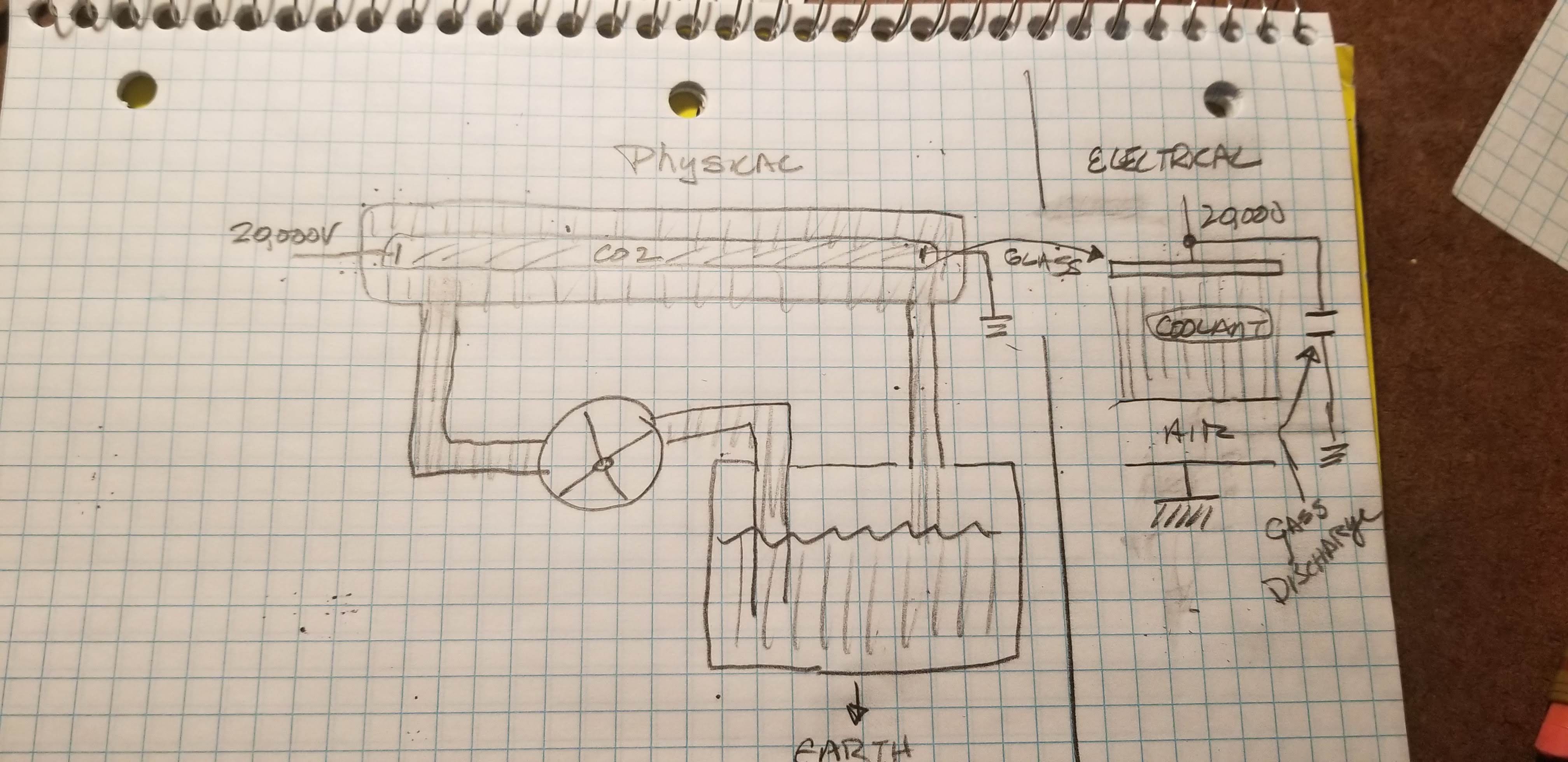
On the other hand you have 20,000 volts across surface of glass (laser tube) on the other side of which is an area of coolant whose other surface is connected to air (another capacitor)

The tubes surface is large and the coolant itself has substantial surface that is connected to air. I would expect the flow of current to be higher if that water was more of a conductor than a dielectric. i.e. a more leaky capacitor.

The area represented by the surface of the water jacket is substantial, the voltage is substantial so its not hard to imagine a small change in the dielectric could increase the current beyond the supply’s design capacity which is in the range of 32ma.

Also consider that the voltage applied to the tube of water is a large spike of 20,000 volts with low current until the gas ionizes at which time there is massive current and a huge drop in voltage. So there is a period of time, albeit short, that this capacitor has large voltage across it.

All theory so far, as there is no real empirical proof this is the circuit mechanism.

As an interesting side my research showed that professional laser cutter systems all use distilled water or coolants that have careful control of their conductivity.

All theory’s are still in play… I will have to noodle your ideas more.

If it is controlling the laser with PWM then there’s a change in magnetic field with every pulse. But yeah, low current so small change and high voltage so capacitive coupling makes sense to me now that I’m thinking more about it. (I suppose I should have thought about the capacitors people make for tesla coils.)

I should go back to writing code. I’ll do that now. :slight_smile:

Keep noodling … its how problems get solutions :)!

1 Like

Must - fight - urge - to - connect - capacitance meter - to - tube!
lol