Not sure. Will let you know definitively when I get home.
Actually, it is RMS current.
The 5.6V rating means that if you put 5.6V across each of the coils, it will pull the rated current. (Stepper motors that are not being microstepped can be supplied with their full rated voltage at each step without current regulation; This is where it is a DC rating. However, if the supply is higher voltage, then the current needs to be regulated within the rated maximum, and the current rating is to limit heat, therefore it’s the area under the curve that matters and it’s really an RMS rating.) You are putting 24V across them but then configuring the stepper drivers to limit RMS current based on Vref. Set your potentiometers for 1.4V Vref for 1A rated steppers. You can go slightly under but don’t go over.
Setting the current limits from the firmware is nice if it’s an option, but turning a potentiometer isn’t too hard either. 
The way that the stepper driver limits current to the motor is with a “chopper” PWM circuit that alternately provides full voltage and turns it off, such that the average current is within the max. It controls microstepping by varying the duty cycle for the PWM switching on each of the motor windings. It turns out that at this high frequency, the motor coil is an inductive filter, or integrator, so the motor doesn’t really “see” the PWM signal as long as the frequency is high enough. (Spoiler alert: It is.)
The stepper motor current rating is based on the heat that is produced; if it gets too hot, the permanent magnets will be heated over their curie temperature and lose some of their permanent magnetism, which makes them rather less useful for the motor’s function. That’s why it’s the area under the curve, which in AC terms is “RMS current”, that ultimately matters for a stepper motor rating, and it’s why RMS current (from the stepper controller’s point of view) is actually the same thing as the DC current rating (given the max rated voltage at 100% duty cycle).
2 Likes
Ahh ok that makes sense now. Thanks
The reason to run them at least close to rated current is that with microstepping, torque is much lower, so even though the torque at full steps is probably far more than you need, the microstepping will be more accurate at higher current.
There’s no real point in switching to sensorless homing when you already have limit switches. For my pandemic printer, having firmware control of current means that I can do sensorless homing (didn’t have to install some limit switches) at a very low current, just enough to reliably trigger and not skip steps, but not so high that the machine goes BANG when homing. Other than that, it’s set-and-forget whether it’s firmware or a hardware potentiometer.
1 Like
From the images in the Amazon listing, Rsense is 110mOhm (.11Ohm)
I see that Watterott recommends starting at half the rated current, which would be 0.7V rather than 1.4V, and then increasing by about .1A at a time until it quits skipping steps. I don’t think this is great advice because lack of accuracy in microstepping can be subtle.
If you can figure out what the current was actually set to out of the box you can mimic that.
If you want to split the difference, start with 1V Vref?
1 Like
Thanks for reminding me that it is working with a stepper motor and not a DC motor! My turn to slap my palm to my forehead!
Here is a great quick and simple explanation with pictures and graphs!
https://www.amci.com/industrial-automation-resources/plc-automation-tutorials/stepper-motor-drivers-rms-or-peak-current/
2 Likes
This drove me nuts when I was first playing with stepper motors! I spent a bunch of time with first measuring DC current across a single winding with my VMM, and then the rare experience of actually using all four channels on my oscilloscope to visualize what was going on in a running stepper.
2 Likes
Thanks guys, I’m learning so much here.
2 Likes
Finding and ordering back up hot end thermistors for my A10 turned out not to be as straightforward as one would think it should be.
Installed the TMC2209s and installed a nice custom firmware for the A10.
3 Likes
Been slowly working on calibrating the printer and playing with parameters. Installed a 4mm glass bed and everything is flat and level.
I’ve been going by this site that @HalfNormal pointed out
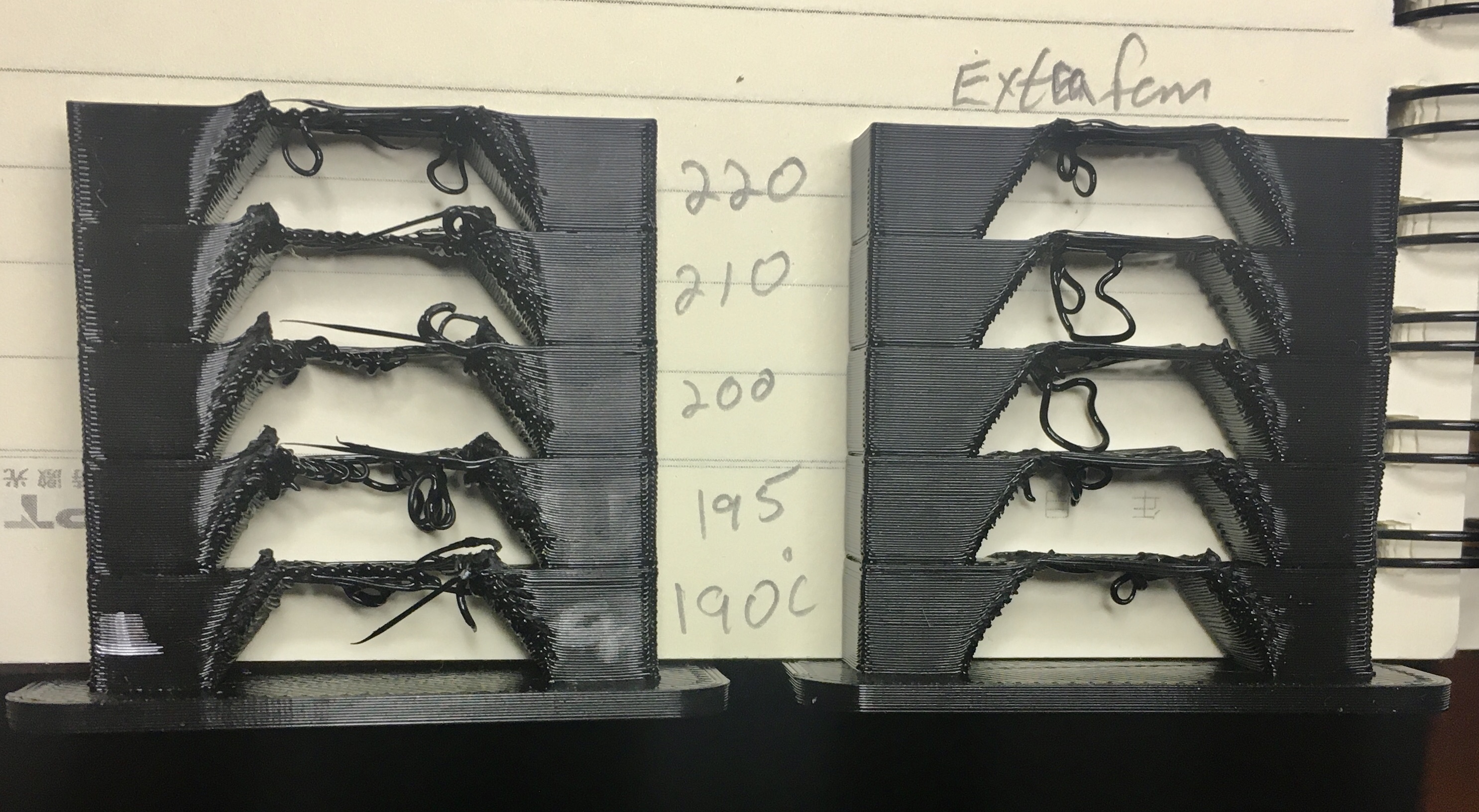
Calibrated the E steps, slicer flow, retraction distance and speed. Been working great. Then I get to temp tuning and things get wonky. He’s set up a temp tower that you can enter extruder temps and generate the G code with the site slicer. Had been printing at 200C with the PLA I’m using and it’s seemed to work fine.
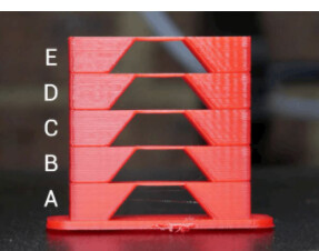
This is what the temp tower is suppose to look like.
This is what I got. ![]()
Front side
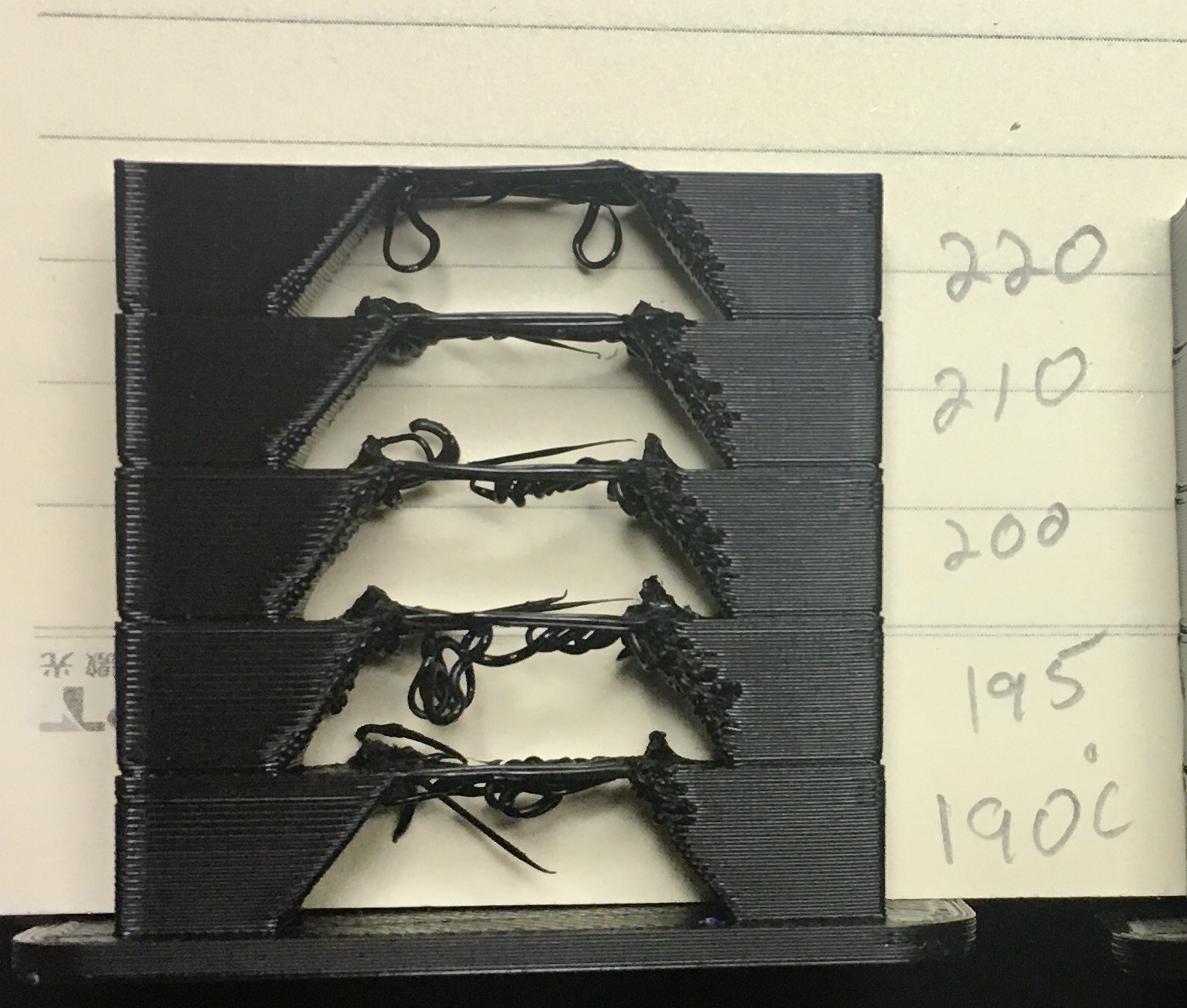
Back side
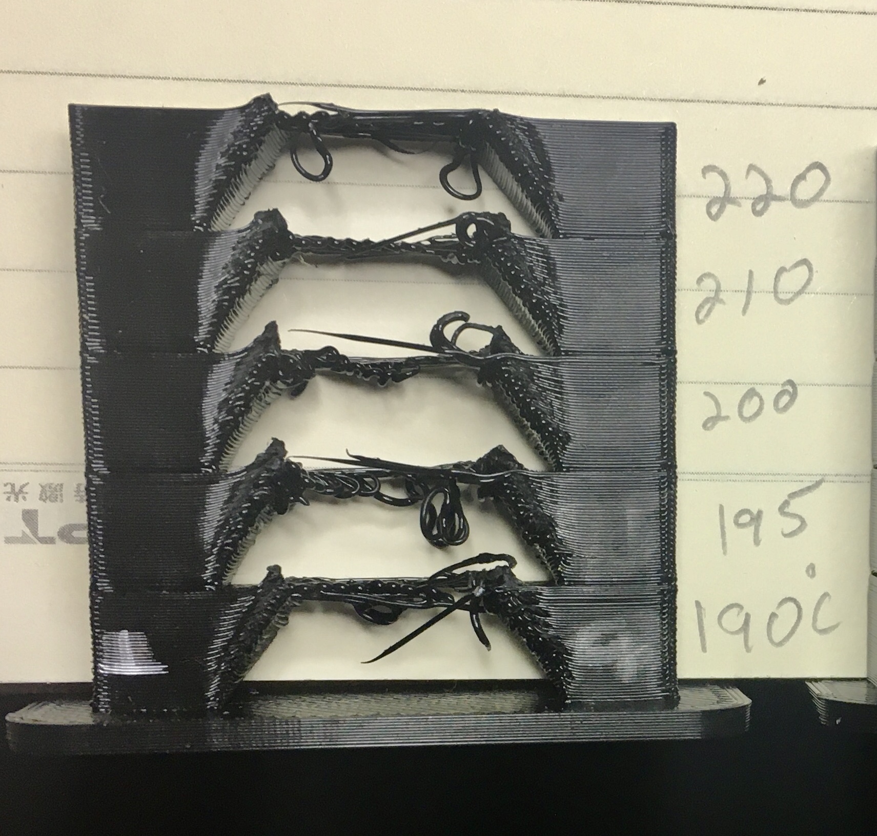
Seemed that I might not have enough cooling for the overhangs especially on the back side
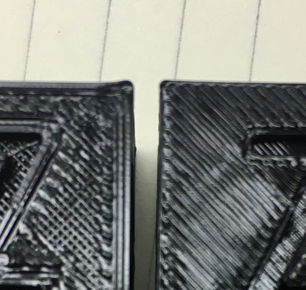
Placed a small personal fan behind the printer and repeated the print. Didn’t completely solve the issue but it’s definitely better
Front Sides Comparison
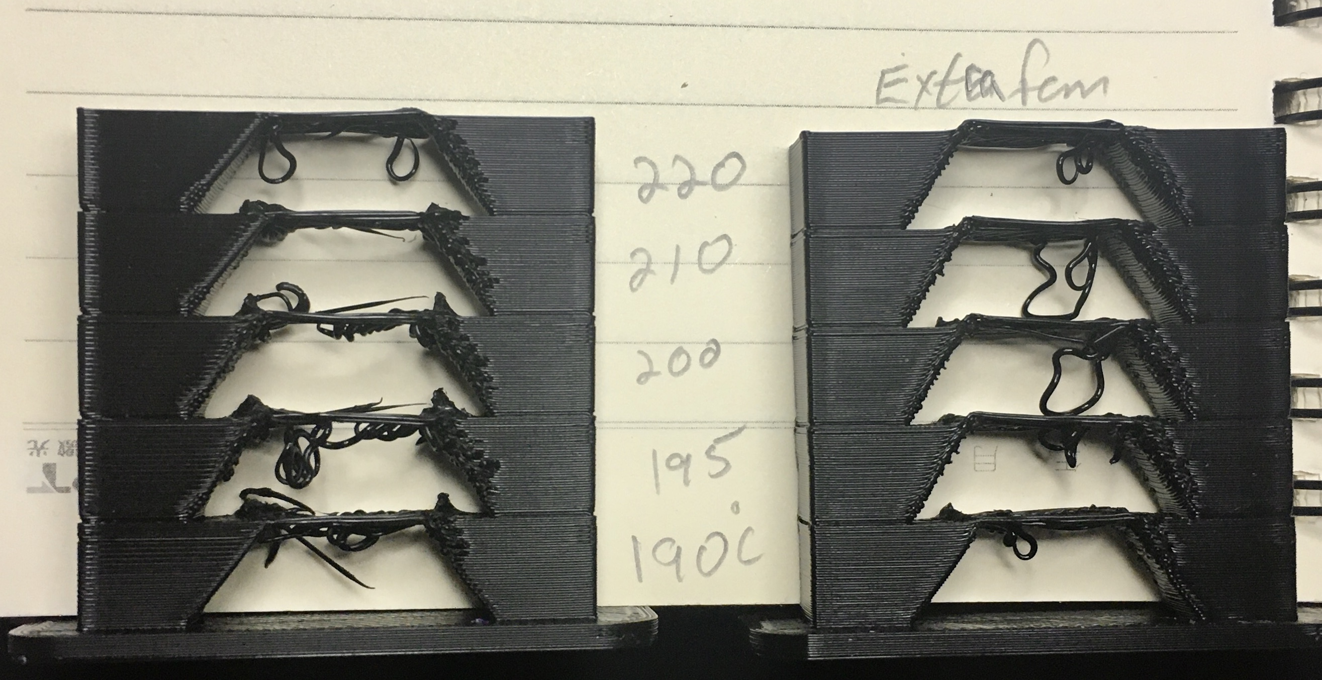
Back Sides Comparison
Any more suggestions? Seems that I might need to add second fan?
Or maybe something like this?
2 Likes
Depending on the brand of pla it’s usually between 200 and 210 for a decent print. I have not personally been able to replicate his Bridges as I end up with something akin to what you get. Unfortunately cooling is a two-way street. Sometimes it’s great and sometimes it’s not and it all depends on the print you’re printing.
Sorry about being ambiguously ambiguous!
1 Like
Ok glad to know it’s not just me. I suspected there might be something with the way his slicer is setting up the print. He provides the .stl file for the tower but then I would need to figure out how to change temp as a function of print height in Prussia slicer  . Sooo many things to learn.
1 Like
First: I don’t concentrate on temperature towers because one of the things I enjoy is working out how to avoid most need for bridges in my designs. When I am designing functional parts, the strength from additional layer adhesion from printing towards the upper end of the range is usually a win for me. I have a used CPAP that I meant to use for remoting cooling and still haven’t gotten around to hooking it up because it turns out it didn’t matter enough to me. However, I’ve read enough to pass on some of what I have learned in case it’s useful.
Most people designing cooling fan ducts (including me) don’t know computational fluid dynamics, and don’t have good intuition for impedance matching in fluid flow. (Air in an open system where all movement is subsonic acts as a fluid system.) Mark Rehorst deleted his reddit account due to all the hate he got merely from saying that you need to test whether you actually get substantial air movement from your cooling setup.
I agree that better cooling looks like it would help. That particular design doesn’t look optimal to me for impedance matching, but this isn’t my area of expertise so you could certainly try it.
But also keep in mind that temperature measurements with thermistors may be more precise than accurate, and temperature specifications for filaments are a wide range. You might try a bit below the recommended range and see what happens to those bridges, including with the extra fan.
If cooling is important to you, there are other things you could try. You could borrow the air pump from your K40 and use latex surgical tubing (the soft stuff) to supply air to a ring something like the one on that part you found. Here are some links that might be useful:
2 Likes
Got Linear Advance enabled in the firmware
![]()
and determined the K value for my filament.
Much sharper corners now.
Feel I got the printer tuned pretty good for now.
Now onto printing real objects. 
First up was a filament arm for the printer I got from thingiverse
Was a two part print and of course the piece that mounted into the frame required a bridge.  Printed that part at 185C and it worked out decently. Just had to do a bit of clean up with a hobby knife and mini file.
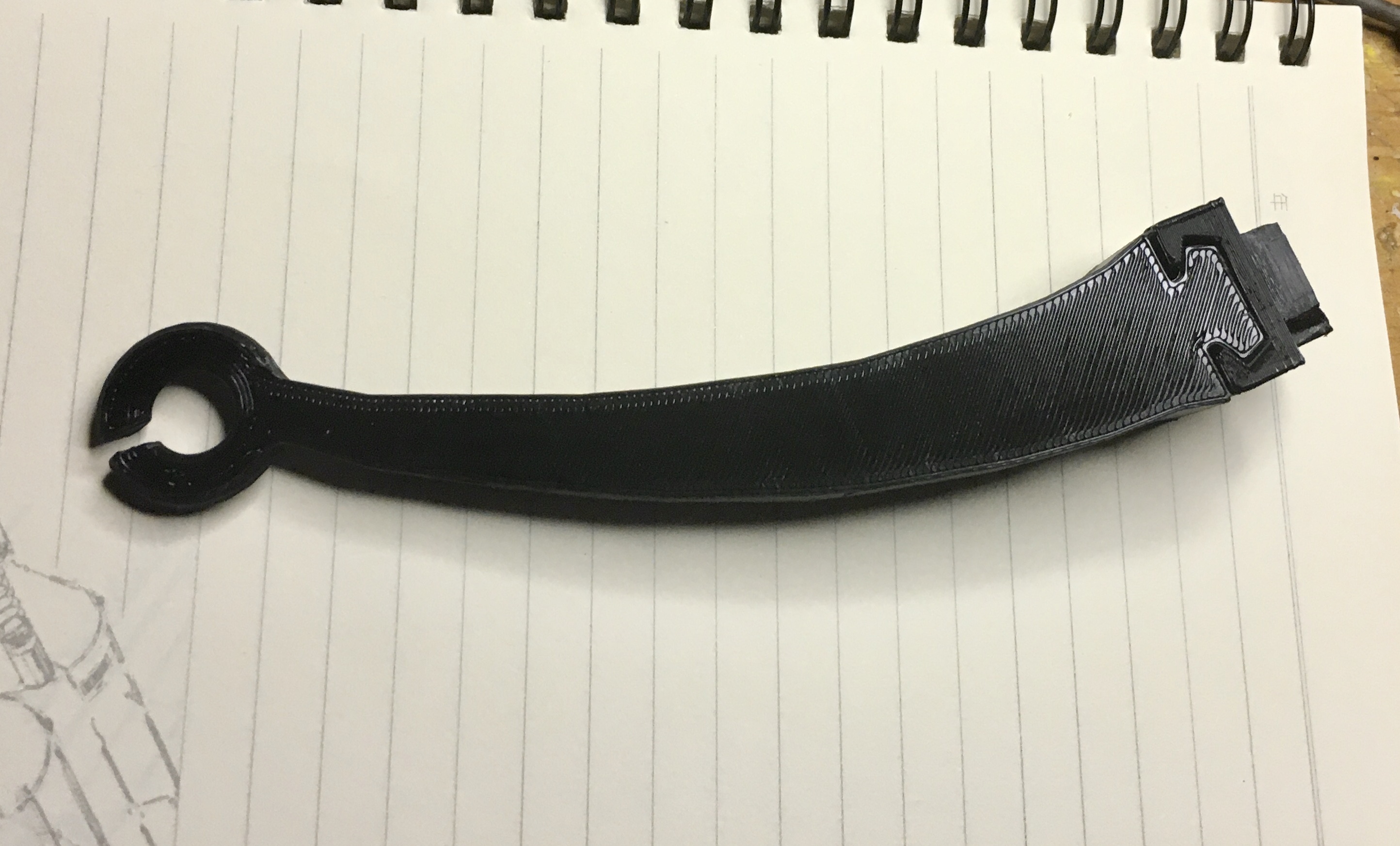
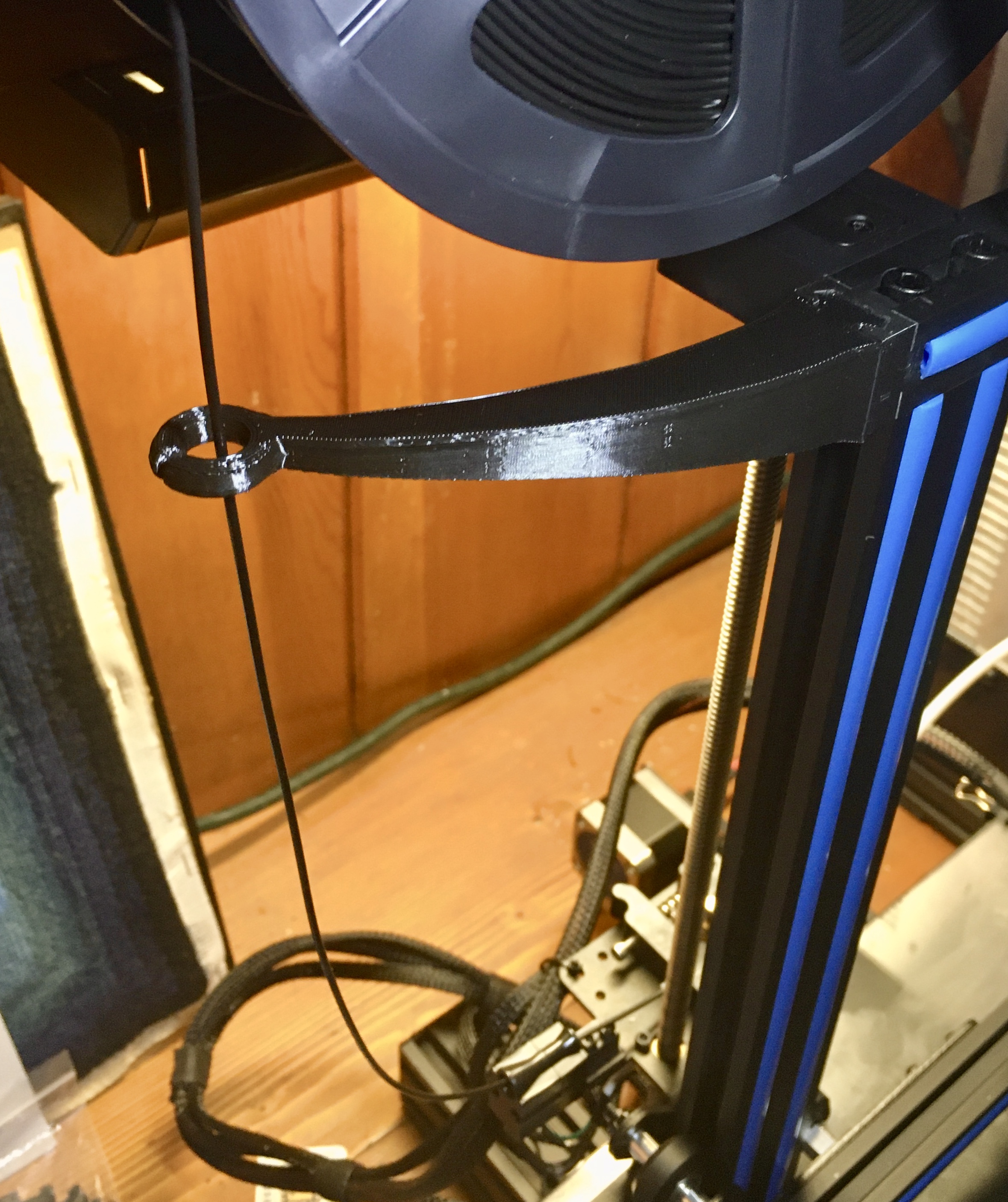
After I installed it, I realized that I didn’t have the spool holder bracket shifted as far to the left edge as it could go. Once I did that it seems that the filament arm might not have really been necessary.  No problem though, it’s all still practice for me.
2 Likes
That reminds me… I do you have a deburring tool? I waited too long after reading lots of “this changed my life” comments — $12 or so, and you’ll thank yourself the first time you use it, if you are anything like me. I now have one at my mill and another at my 3D printer.
2 Likes
Huh, no I do not have a deburring tool. I’ve seen them for metal use when people are doing lathe work but I hadn’t thought of that for plastic too. Thanks for the tip
1 Like
Oh, the ones I’m thinking of aren’t the ones I think of for lathe work. I’m thinking of the swivel-head curved blade units like this:
2 Likes
Ok, yeah that’s the type I was thinking of actually. I meant mill not lathe.
2 Likes