From the images in the Amazon listing, Rsense is 110mOhm (.11Ohm)
I see that Watterott recommends starting at half the rated current, which would be 0.7V rather than 1.4V, and then increasing by about .1A at a time until it quits skipping steps. I don’t think this is great advice because lack of accuracy in microstepping can be subtle.
If you can figure out what the current was actually set to out of the box you can mimic that.
If you want to split the difference, start with 1V Vref?
This drove me nuts when I was first playing with stepper motors! I spent a bunch of time with first measuring DC current across a single winding with my VMM, and then the rare experience of actually using all four channels on my oscilloscope to visualize what was going on in a running stepper.
Been slowly working on calibrating the printer and playing with parameters. Installed a 4mm glass bed and everything is flat and level.
I’ve been going by this site that @HalfNormal pointed out
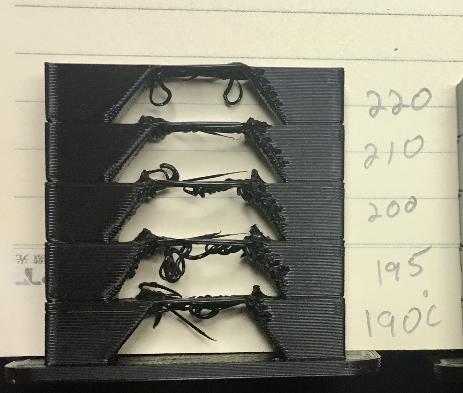
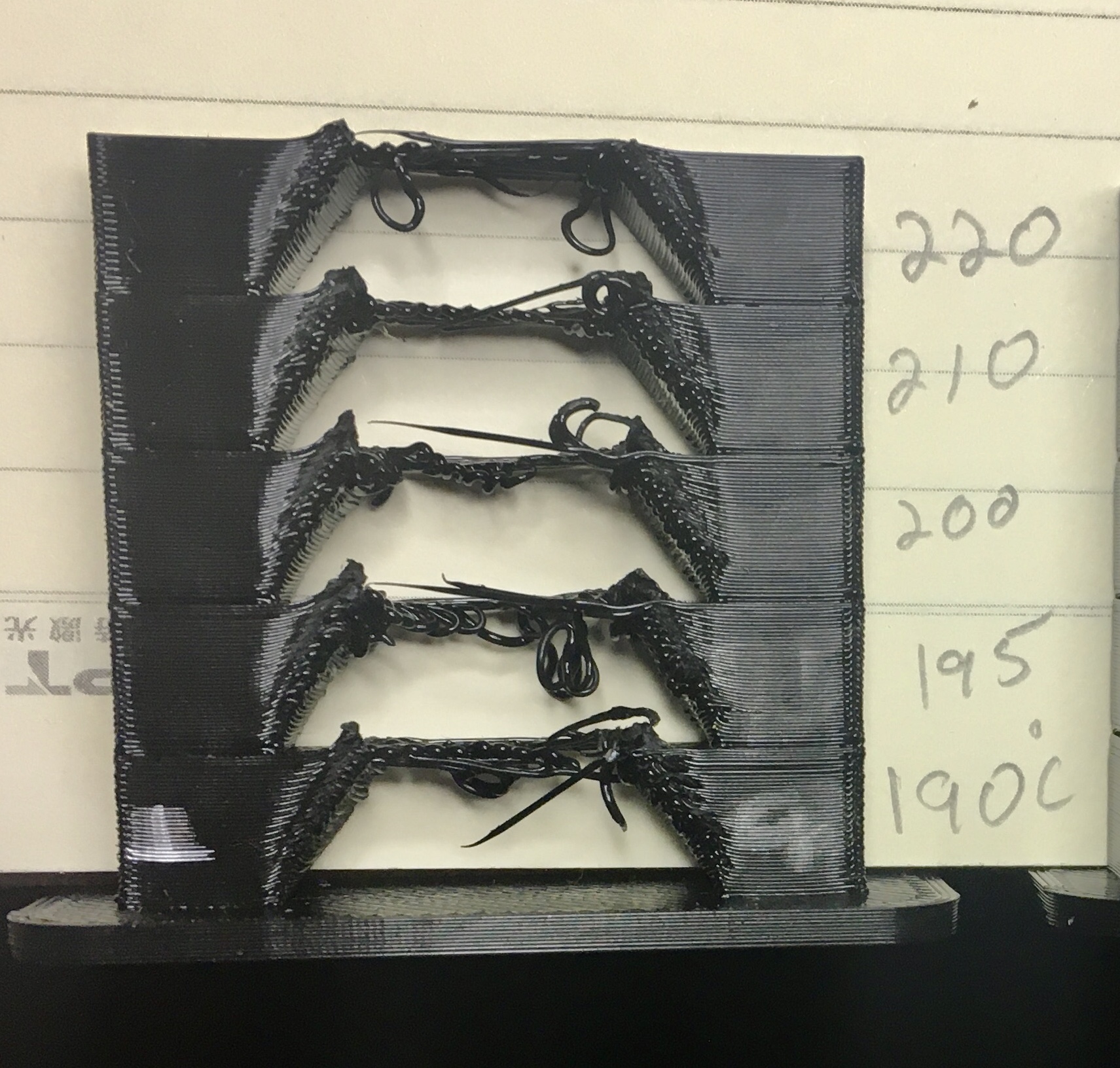
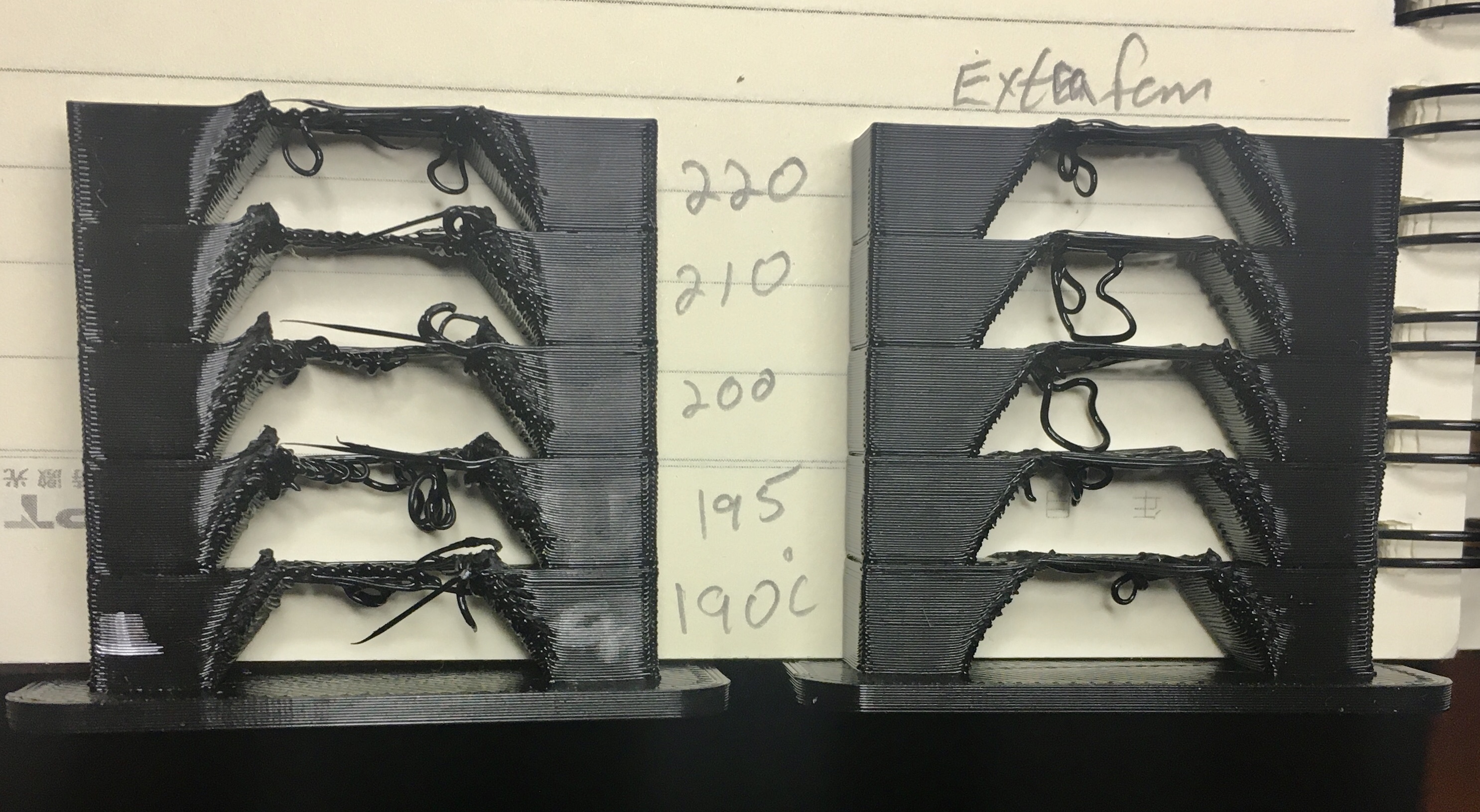
Calibrated the E steps, slicer flow, retraction distance and speed. Been working great. Then I get to temp tuning and things get wonky. He’s set up a temp tower that you can enter extruder temps and generate the G code with the site slicer. Had been printing at 200C with the PLA I’m using and it’s seemed to work fine.
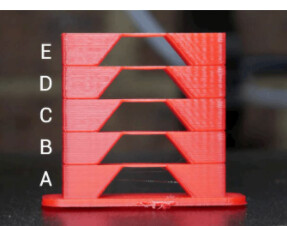
This is what the temp tower is suppose to look like.
Depending on the brand of pla it’s usually between 200 and 210 for a decent print. I have not personally been able to replicate his Bridges as I end up with something akin to what you get. Unfortunately cooling is a two-way street. Sometimes it’s great and sometimes it’s not and it all depends on the print you’re printing.
Sorry about being ambiguously ambiguous!
Ok glad to know it’s not just me. I suspected there might be something with the way his slicer is setting up the print. He provides the .stl file for the tower but then I would need to figure out how to change temp as a function of print height in Prussia slicer . Sooo many things to learn.
First: I don’t concentrate on temperature towers because one of the things I enjoy is working out how to avoid most need for bridges in my designs. When I am designing functional parts, the strength from additional layer adhesion from printing towards the upper end of the range is usually a win for me. I have a used CPAP that I meant to use for remoting cooling and still haven’t gotten around to hooking it up because it turns out it didn’t matter enough to me. However, I’ve read enough to pass on some of what I have learned in case it’s useful.
Most people designing cooling fan ducts (including me) don’t know computational fluid dynamics, and don’t have good intuition for impedance matching in fluid flow. (Air in an open system where all movement is subsonic acts as a fluid system.) Mark Rehorst deleted his reddit account due to all the hate he got merely from saying that you need to test whether you actually get substantial air movement from your cooling setup.
I agree that better cooling looks like it would help. That particular design doesn’t look optimal to me for impedance matching, but this isn’t my area of expertise so you could certainly try it.
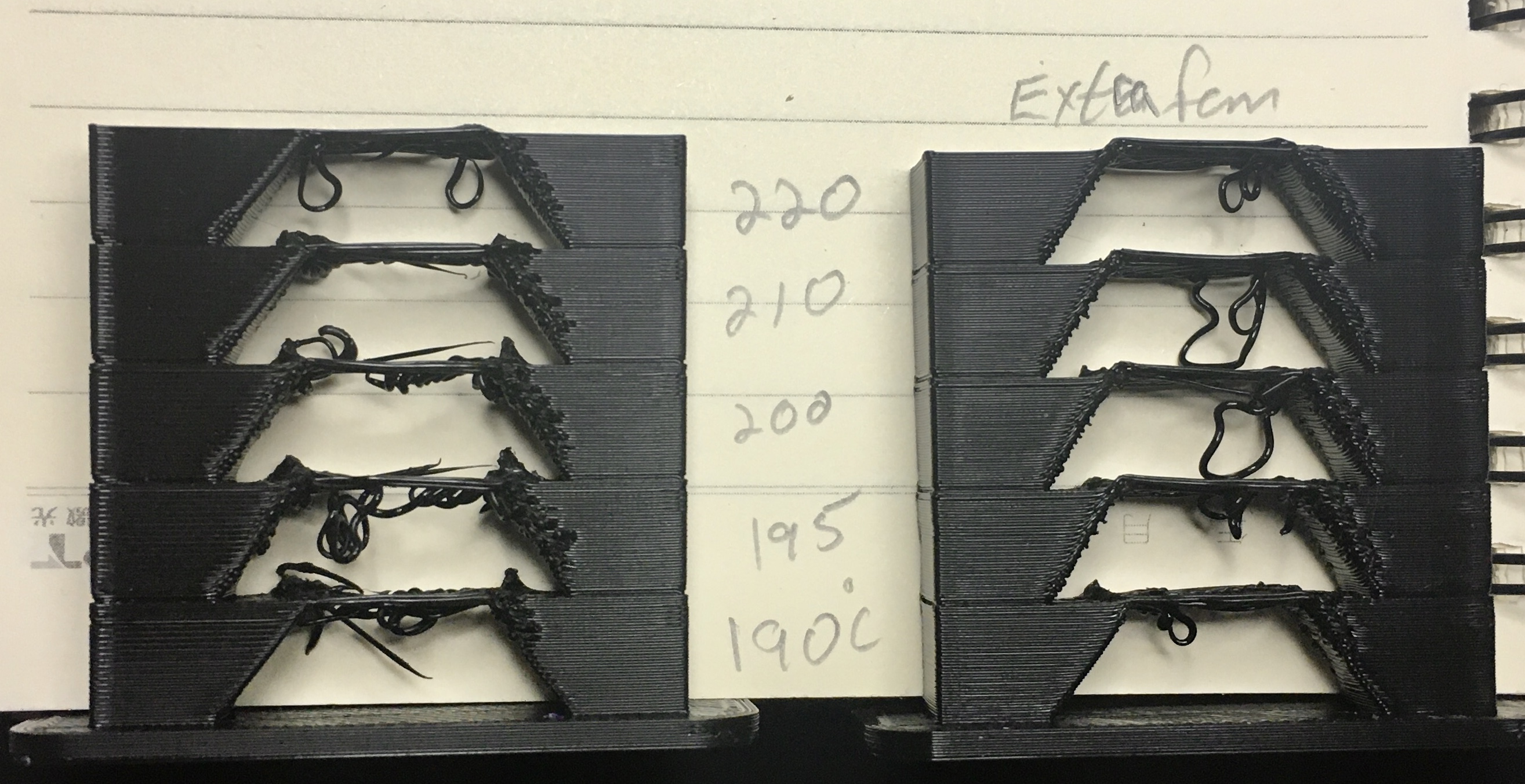
But also keep in mind that temperature measurements with thermistors may be more precise than accurate, and temperature specifications for filaments are a wide range. You might try a bit below the recommended range and see what happens to those bridges, including with the extra fan.
If cooling is important to you, there are other things you could try. You could borrow the air pump from your K40 and use latex surgical tubing (the soft stuff) to supply air to a ring something like the one on that part you found. Here are some links that might be useful:
First up was a filament arm for the printer I got from thingiverse
Was a two part print and of course the piece that mounted into the frame required a bridge. Printed that part at 185C and it worked out decently. Just had to do a bit of clean up with a hobby knife and mini file.
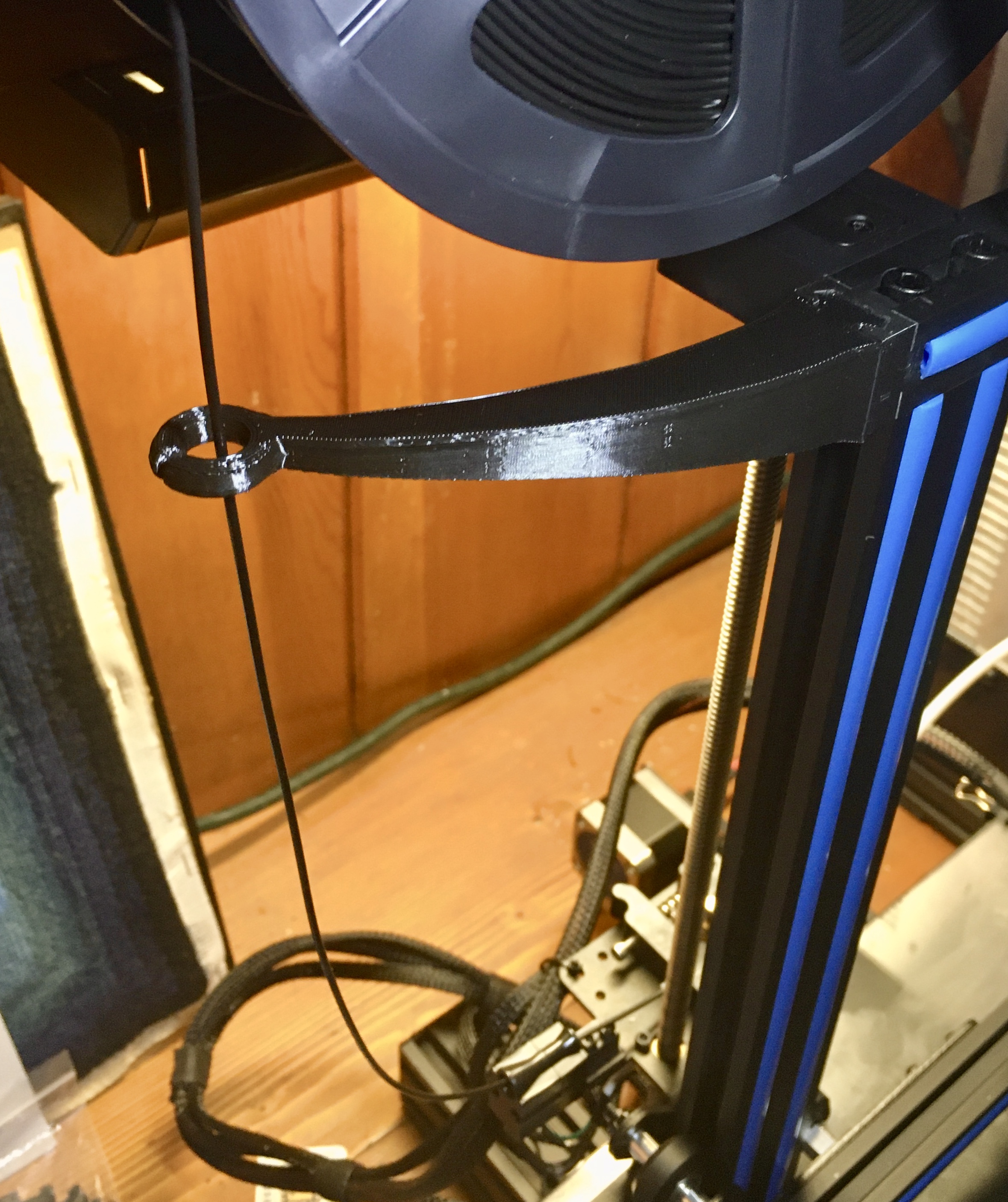
After I installed it, I realized that I didn’t have the spool holder bracket shifted as far to the left edge as it could go. Once I did that it seems that the filament arm might not have really been necessary. No problem though, it’s all still practice for me.
That reminds me… I do you have a deburring tool? I waited too long after reading lots of “this changed my life” comments — $12 or so, and you’ll thank yourself the first time you use it, if you are anything like me. I now have one at my mill and another at my 3D printer.
Huh, no I do not have a deburring tool. I’ve seen them for metal use when people are doing lathe work but I hadn’t thought of that for plastic too. Thanks for the tip
Tonight’s adventure in 3d printing involves figuring out how to print with supports. I have very quickly figured out that less is often more when it comes to supports and the ability to remove them afterward.
Still using PrusaSlicer so I’m going through the knowledgebase figuring out what the parameters mean.

 . Sooo many things to learn.

 Printed that part at 185C and it worked out decently. Just had to do a bit of clean up with a hobby knife and mini file.
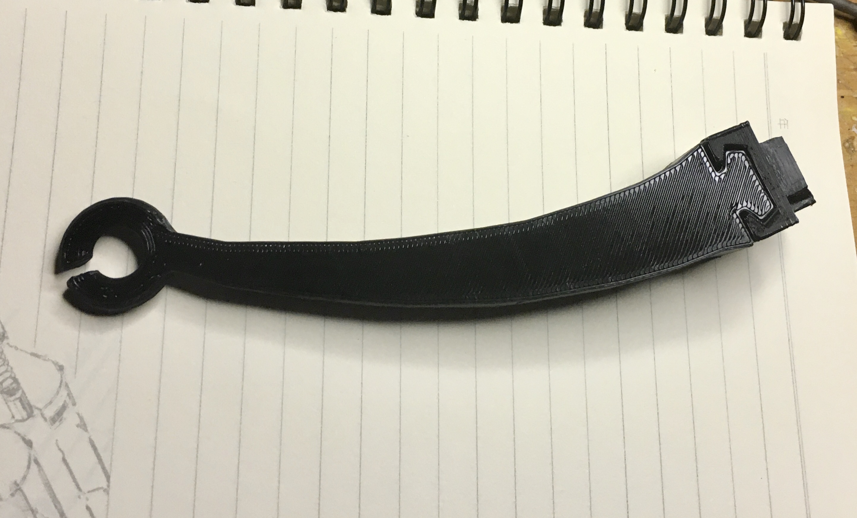
 No problem though, it’s all still practice for me.
  You guys have been a big help in answering my questions.