Started working on this at:
It’s on GitHub at:
but needs a few more modules.
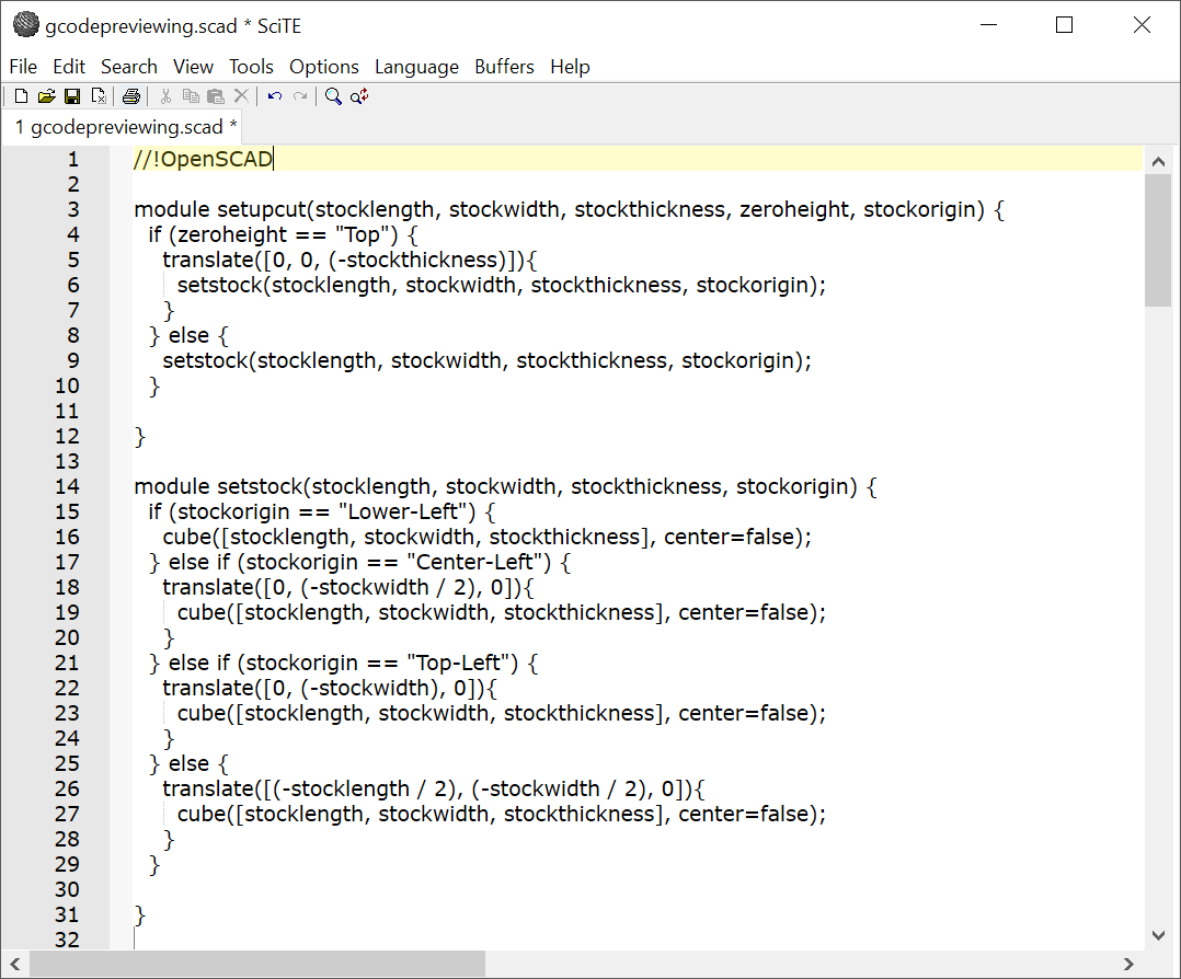
First is setting up the cut:
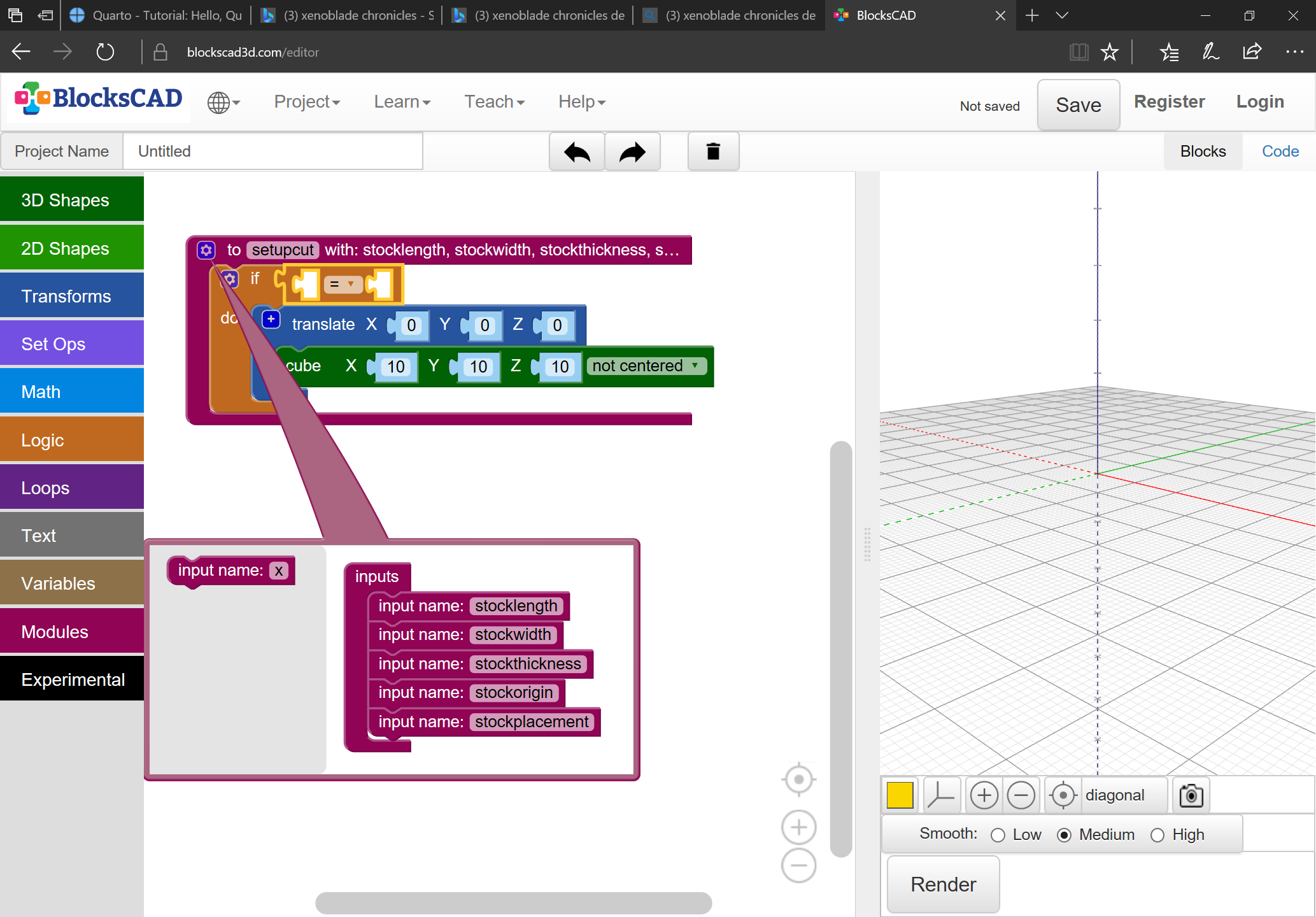
There are 4 possible positions:


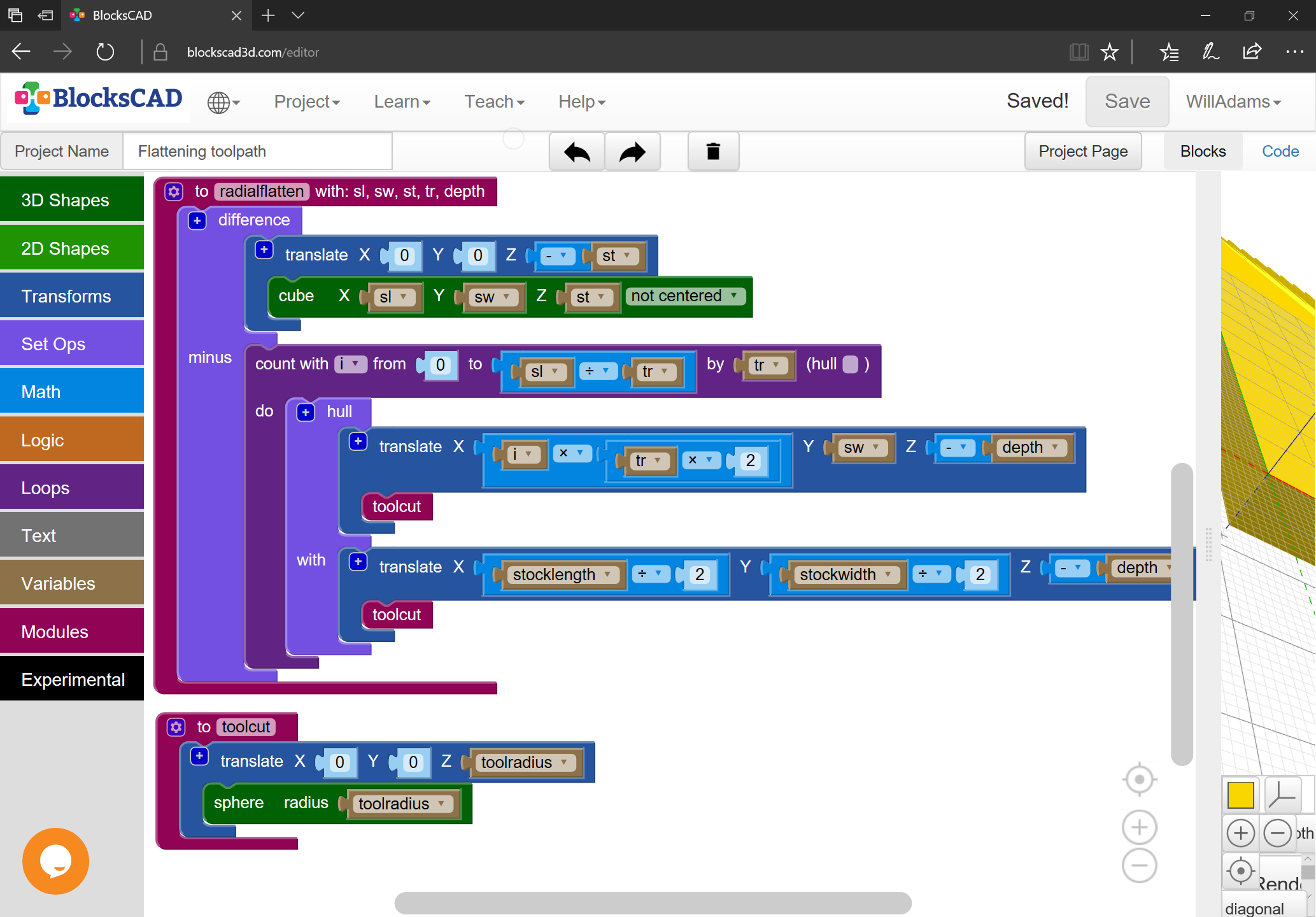
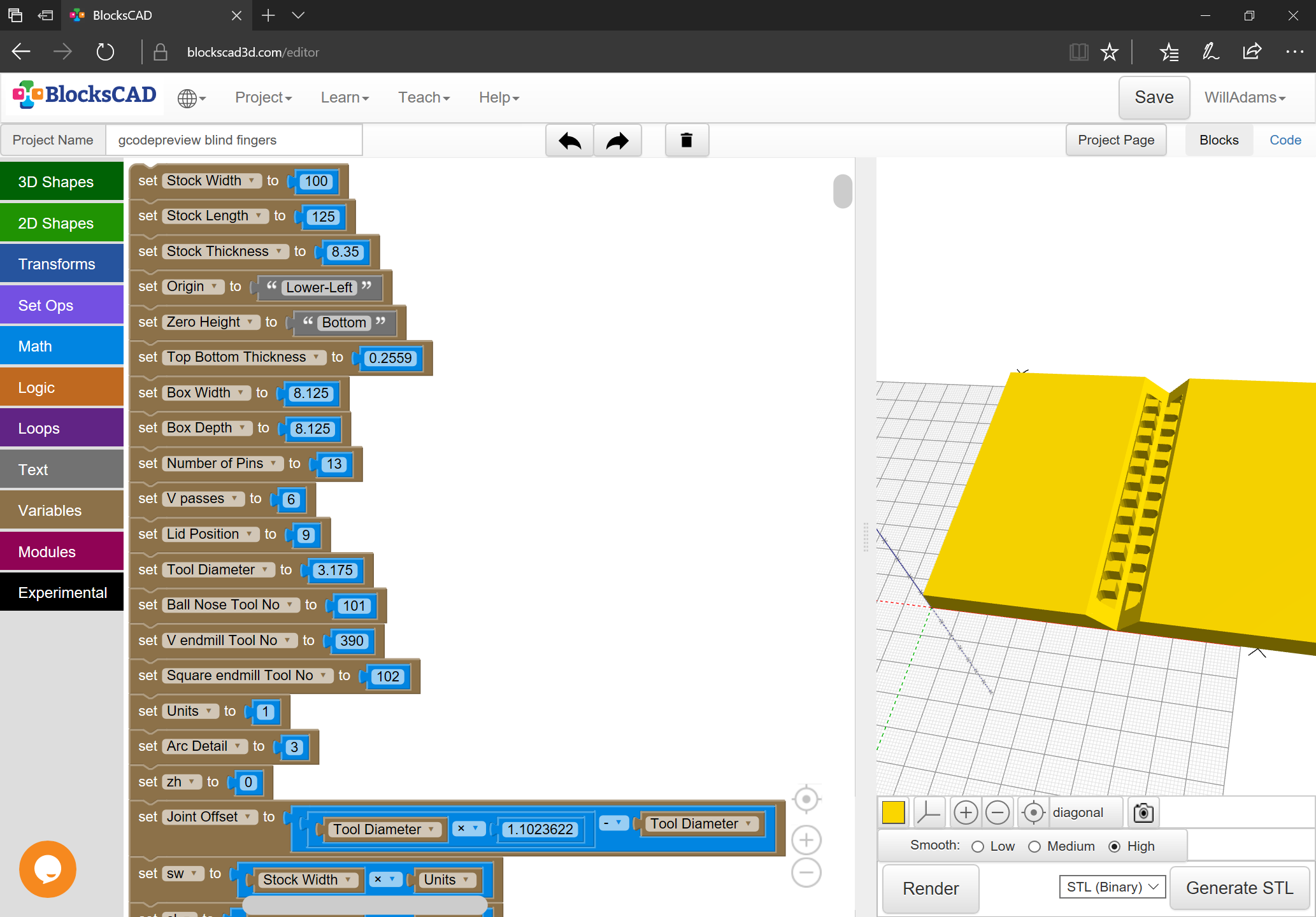
For those who are curious, the BlockSCAD file is at:
Started working on this at:
It’s on GitHub at:
but needs a few more modules.
First is setting up the cut:
There are 4 possible positions:
For those who are curious, the BlockSCAD file is at:
Next, we transfer the code into the library which is being imported into RapCAD:
and begin adding the writeln() commands for it:
writeln("(STOCK/BLOCK, ",stocklength,", ",stockwidth,", ",stockthickness,")");
writeln("G90");
writeln("G21");
writeln("(Move to safe Z to avoid workholding)");
writeln("G53G0Z-5.000");
writeln("M05");
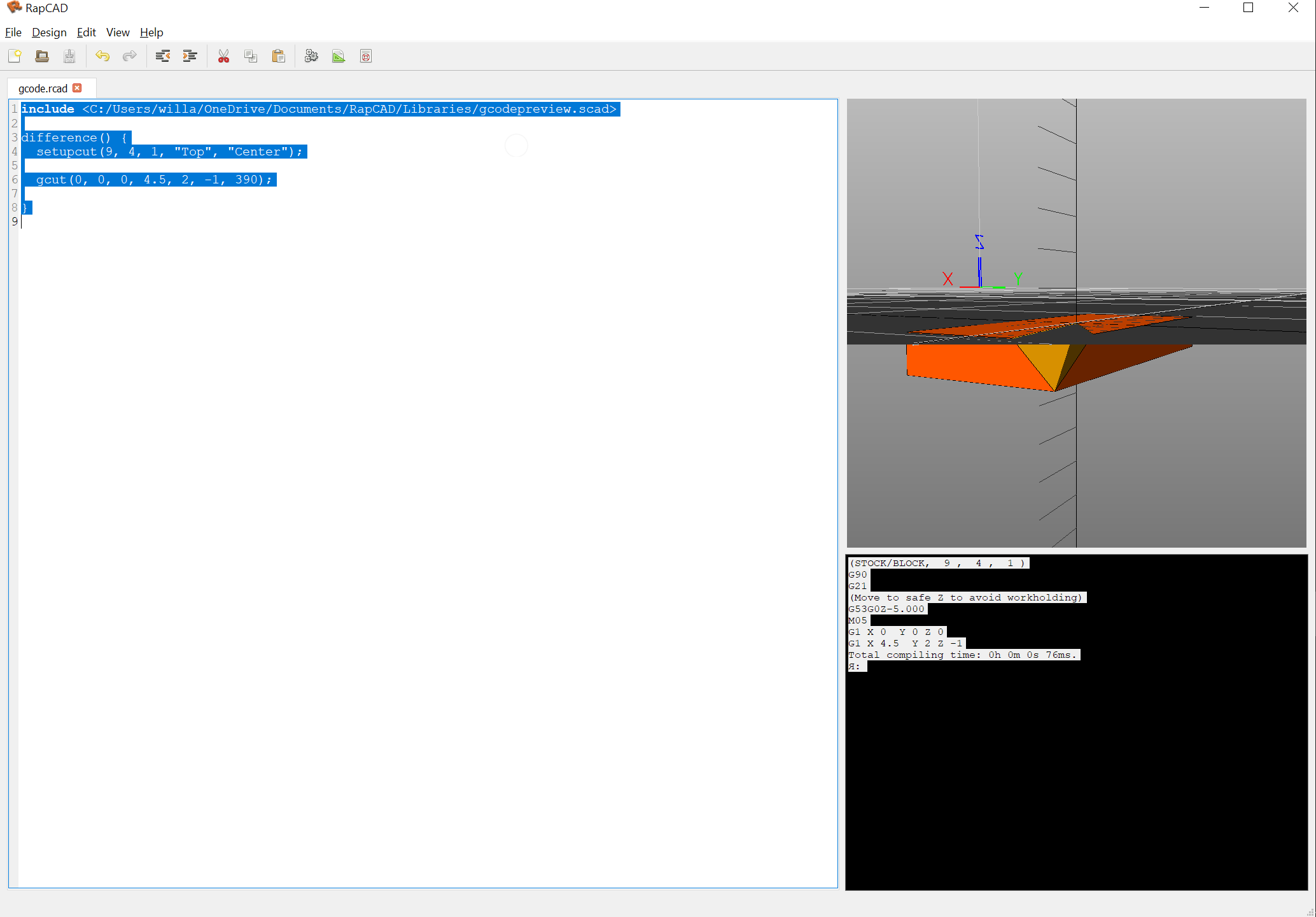
With them in place, it is possible to create a file:
include <C:/Users/willa/OneDrive/Documents/RapCAD/Libraries/gcodepreview.scad>

difference() {
  setupcut(9, 4, 1, "Top", "Center");

  gcut(0, 0, 0, 4.5, 2, -1, 390);

}
which renders as expected:
and generates the expected G-code:
(STOCK/BLOCK,  9 ,  4 ,  1 )
G90
G21
(Move to safe Z to avoid workholding)
G53G0Z-5.000
M05
G1 X 0  Y 0 Z 0
G1 X 4.5  Y 2 Z -1
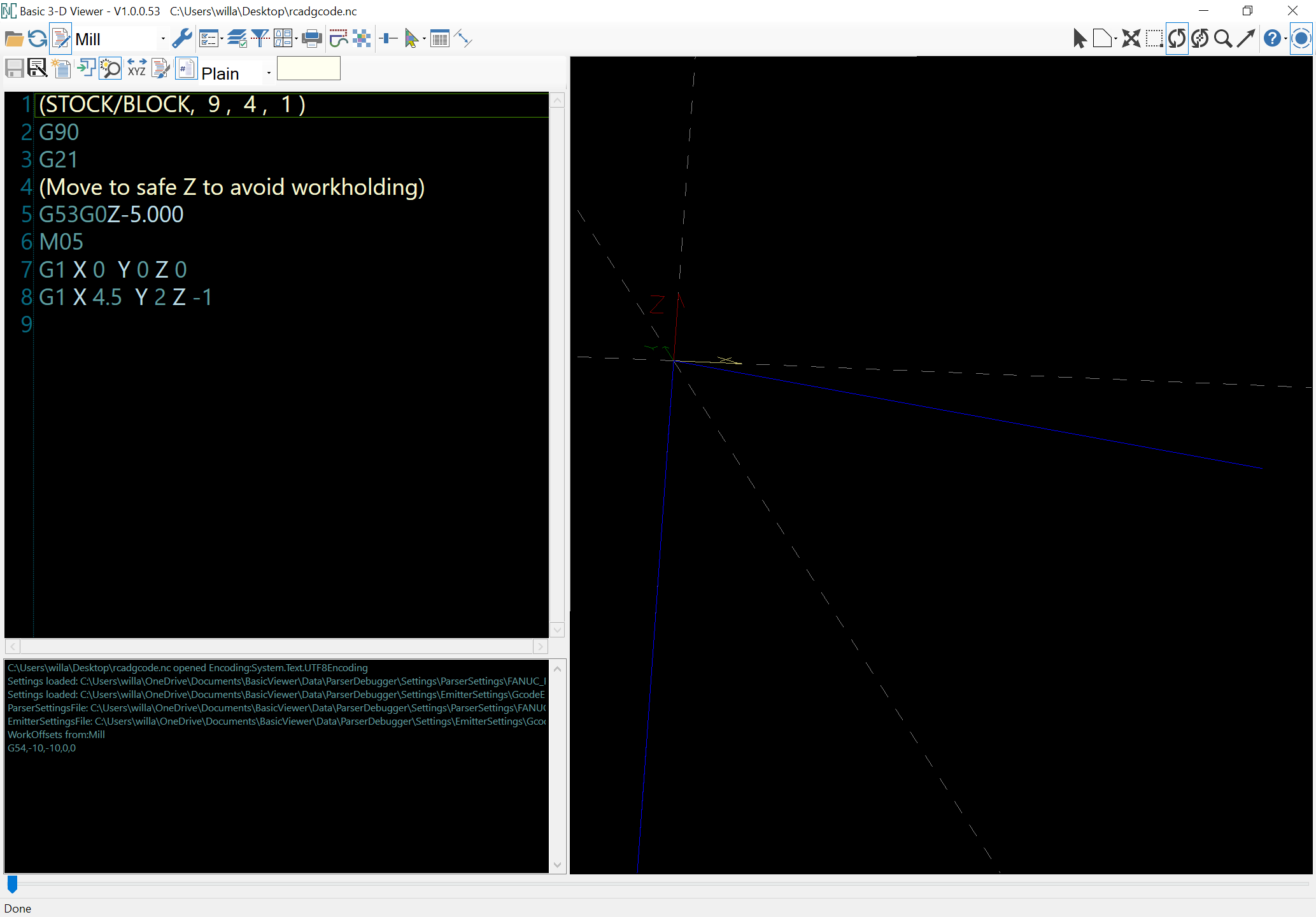
which previews as expected:
So the next module can be added.
Next module is for tool changes:
module toolchange(toolno) {
writeln("(TOOL/MILL,",toolno,")");
writeln(str("M6T",toolno));
}
Other requirements for G-code are:
and a requirement for cutting is to plunge which often requires a different feedrate — so arguably one could combine these.
Rapids should be pretty straight-forward, something like:
module rapid(bx, by, bz, ex, ey, ez) {
	writeln("G0 X",bx," Y", by, "Z", bz);
	writeln("G0 X",ex," Y", ey, "Z", ez);
  hull(){
    translate([bx, by, bz]){
      select_tool(102);
    }
    translate([ex, ey, ez]){
      select_tool(102);
    }
  }
}
Many commands, and the overall state of the program won’t make much sense w/o a few additional variable definitions:
Because of how tools are defined, it will only be possible to use metric.
The big difficulty here is the difference between G-code having access to, working w/ the current machine state, and OpenSCAD lacking that (programming a full machine simulation is left as an exercise for the reader).
In particular, the G53 command allows movements relative to the machine origin — the merits of adding additional variables for machine dimensions and offset from origin might make for an interesting discussion.
Given this, it looks like at a minimum either pairs of commands are needed:
Or, one has only the latter sort and any movement has to be programmed on that basis — the first movement would be in the setupcut module:
(Move to safe Z to avoid workholding)
G53G0Z-5.000
and should allow for a safe move down to XY origin at retractheight.
Lastly, for instances when one is doing a single cut, one will want to be able to loop w/ a plunge at one end, and a retract at the other:
module plungegcutretract(bx, by, bz, ex, ey, ez, tn, retract) {
rapid(bx, by, retract, bx, by, bz)
gcut(bx, by, bz, ex, ey, ez, tn)
rapid(ex, ey, ez, ex, ey, retract)
}
This should allow cuts using loops such as:
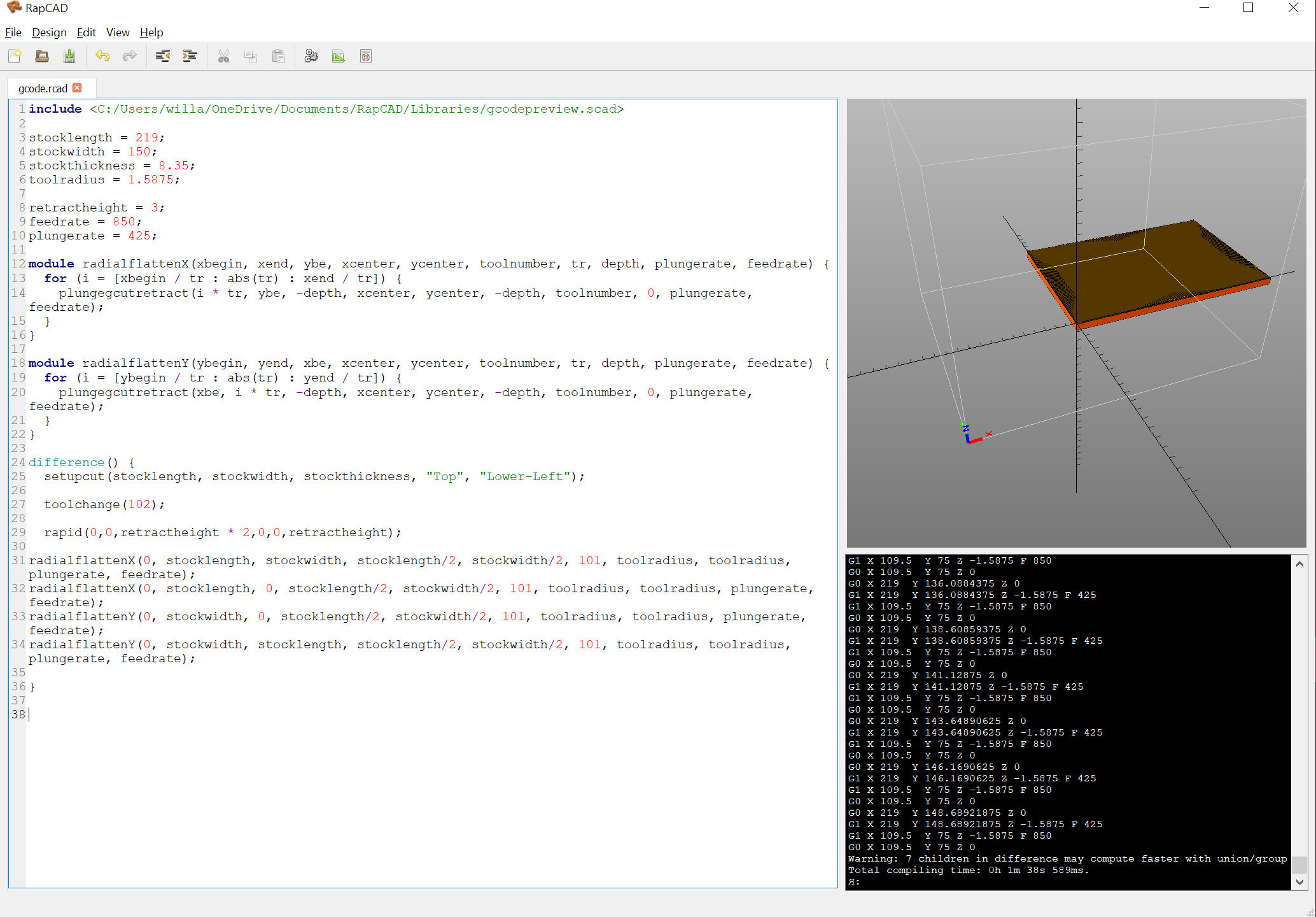
After adding/adjusting modules (updated at: gcodepreview/gcodepreviewing.scad at main · WillAdams/gcodepreview · GitHub )
we can make a file like to:
include <C:/Users/willa/OneDrive/Documents/RapCAD/Libraries/gcodepreview.scad>

stocklength = 219;
stockwidth = 150;
stockthickness = 8.35;
toolradius = 1.5875;

retractheight = 3;
feedrate = 850;
plungerate = 425;

module radialflattenX(xbegin, xend, ybe, xcenter, ycenter, toolnumber, tr, depth, retract, plungerate, feedrate) {
  for (i = [xbegin / tr : abs(tr) : xend / tr]) {
    plungegcutretract(i * tr, ybe, -depth, xcenter, ycenter, -depth, toolnumber, retract, plungerate, feedrate);
  }
}

module radialflattenY(ybegin, yend, xbe, xcenter, ycenter, toolnumber, tr, depth, retract, plungerate, feedrate) {
  for (i = [ybegin / tr : abs(tr) : yend / tr]) {
    plungegcutretract(xbe, i * tr, -depth, xcenter, ycenter, -depth, toolnumber, retract, plungerate, feedrate);
  }
}

difference() {
setupcut(stocklength, stockwidth, stockthickness, “Top”, “Lower-Left”);
  toolchange(101);

  rapid(0,0,retractheight * 2,0,0,retractheight);

radialflattenX(0, stocklength, stockwidth, stocklength/2, stockwidth/2, 101, toolradius, toolradius, retractheight, plungerate, feedrate);
radialflattenX(0, stocklength, 0, stocklength/2, stockwidth/2, 101, toolradius, toolradius, retractheight, plungerate, feedrate);
radialflattenY(0, stockwidth, 0, stocklength/2, stockwidth/2, 101, toolradius, toolradius, retractheight, plungerate, feedrate);
radialflattenY(0, stockwidth, stocklength, stocklength/2, stockwidth/2, 101, toolradius, toolradius, retractheight, plungerate, feedrate);

}
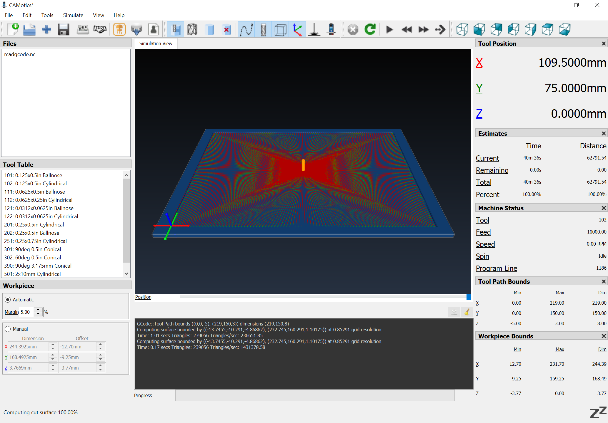
which renders as:
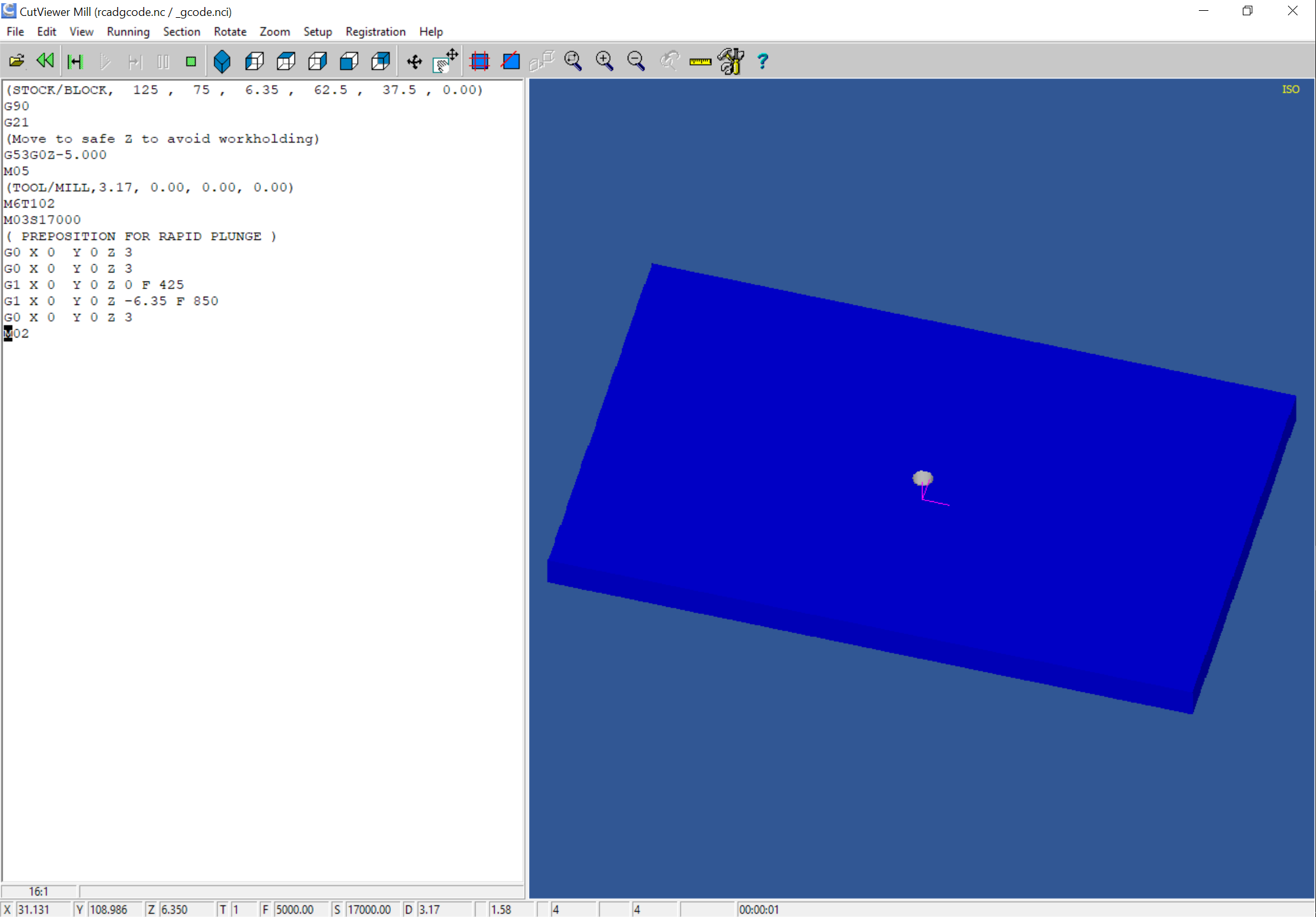
and loads into CAMotics w/o errors as:
Next is working out how to do more than one layer of cuts — I don’t think OpenSCAD/RapCAD have tools which are suited to solving for a number of internal passes, so this will probably need to be brute-forced/designed into the model.
Probably modules which model full-depth plunges in OpenSCAD (to try to limit model complexity) while outputting the necessary depth per pass iterations until one reaches a full depth of cut in G-code will work.
First out of the gate is probably a drill command which will be used for dogbones in joinery.
Reviewing things, the first thing is a switch for enabling/disabling G-code generation, so we add a variable:
generategcode = false;
and wrap all instances of writing out G-code in suitable tests:
if (generategcode == true) {
	writeln("G0 X",ex," Y", ey, "Z", ez);
}
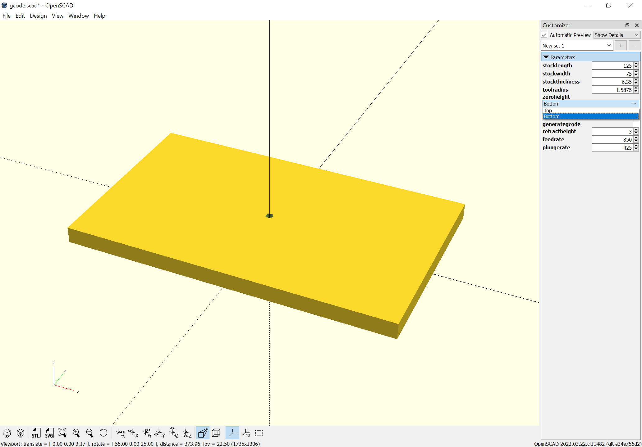
With this in place, it is possible to disable G-code generation and use OpenSCAD for working with the file:
Updated things to allow all possible stock positions:
Top and Bottom:
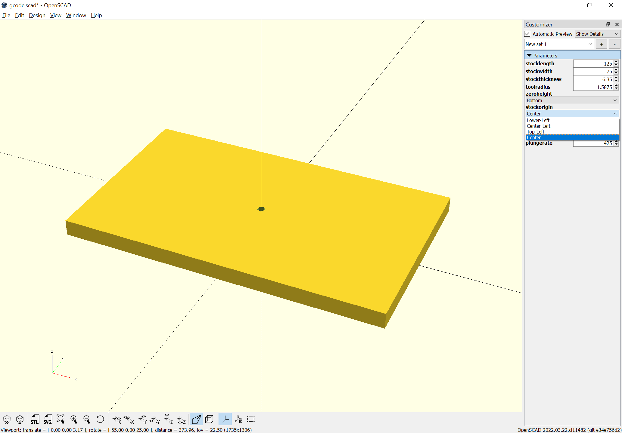
and Lower-Left, Center-Left, Top-Left, and Center:
and when G-code is generated, there are comments which a 3D previewer can use to set the display of the stock and its position to match:
A more useful project, joinery:
https://www.blockscad3d.com/community/projects/1478465
The Vertical direction is done, and one may do both, odd, or even sides:
Next up is transferring this into RapCAD so as to get G-code, then once the concept is proved out, doing the code for the horizontal option.
First, a bit of testing — had to tweak the length of the fingers so that when two pieces are assembled, and one gets the intersection of them:
there is essentially nothing — file for that here:
cncjoinery.scad (1.5 KB)
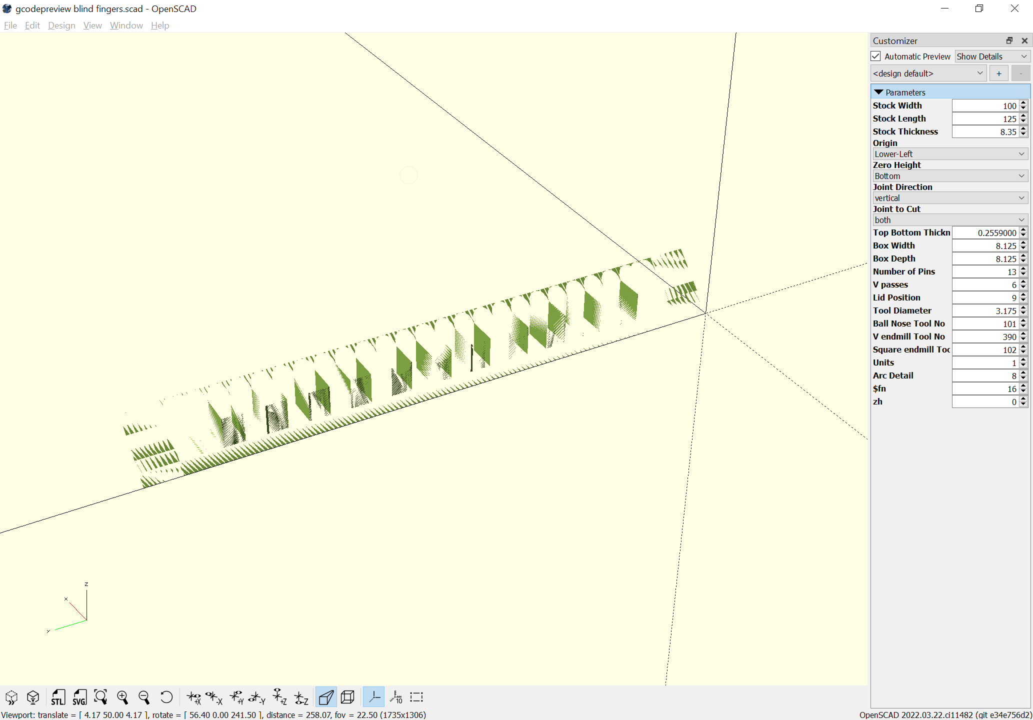
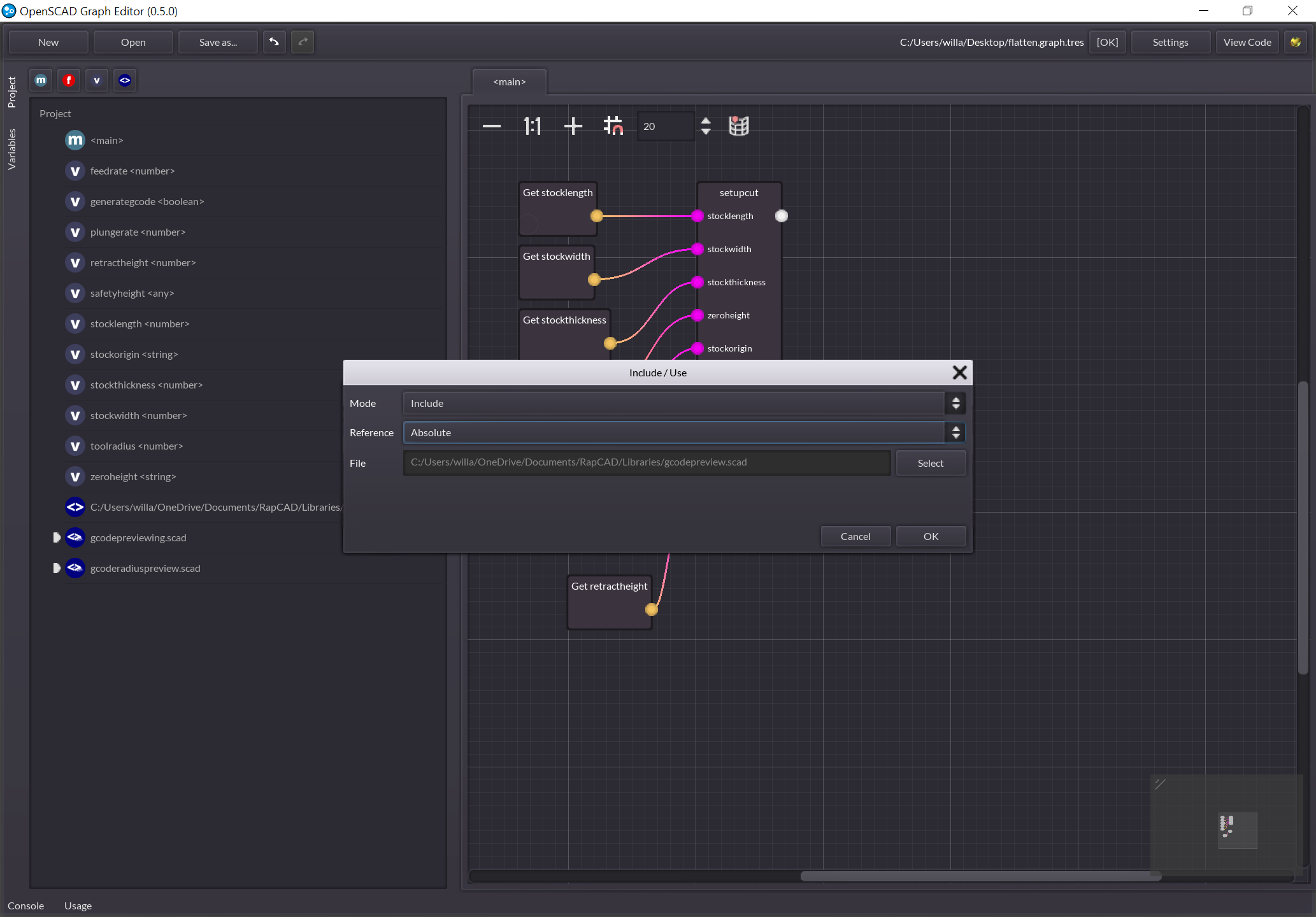
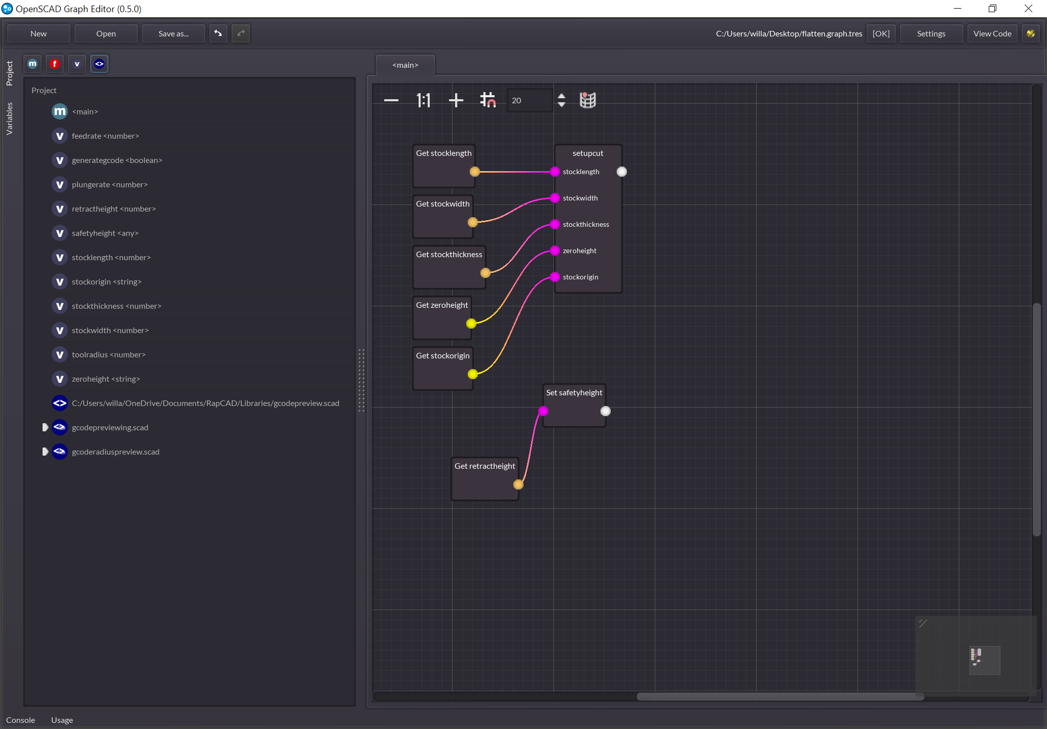
Revisiting this in OSGE:
Start by loading the gcodepreview module:
(note that the module should be "include"d rather than "use"d)
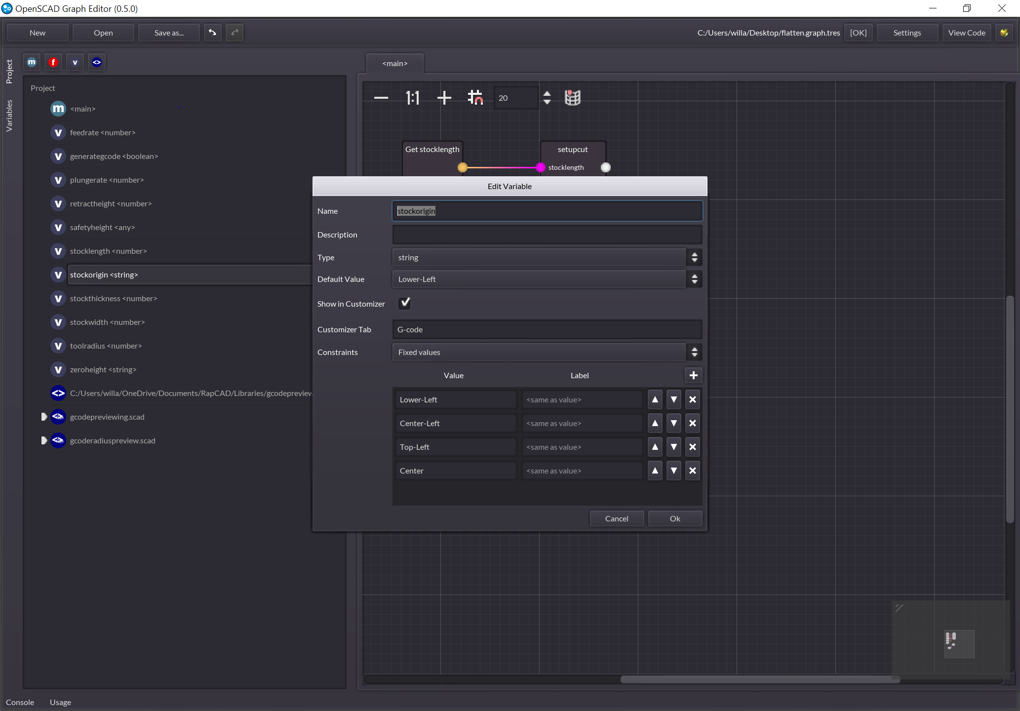
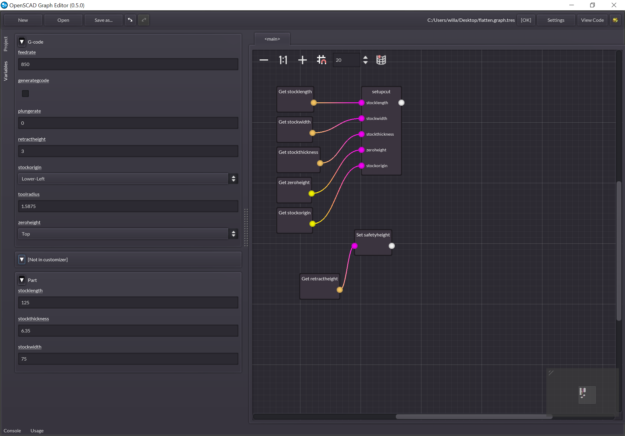
Then it is necessary to set up all of the variables which will be required:
Note that Customizer support allows one to set up drop-down menus and so forth.
Started writing this all up at:
and have just uploaded an updated version to GitHub, as well as finished up a basic first pass at the above on gitbook.