Here we go! This will be a before, during and after restoration with upgrades/mods. I picked this machine up for $120 because the previous owner removed parts to put in his K40 and didn’t have anymore use for it. I like calling this model the mother of K40s because it appears to be the model they cloned from, except the cut area is larger, sheet metal is thicker, the gantry is aluminum, the entire unit, including the tube bay comes apart and it has dual linear rails!
Many of the components will need reattached, which won’t be a problem. The gantry was no longer bolted down, but surprisingly didn’t get bent and twisted during shipment. Unfortunately, the acrylic window and tube were busted thanks to the excellent handling of FedEx.
The controllers they put in these are getting obsolete and the Cohesion3D board will be an amazing improvement!
This is how the unit looked before receiving it. The following photos are courtesy of: @Starla .
Nothing a little elbow grease can’t handle.

Where’s the stepper motor?

There it is, on the floor!

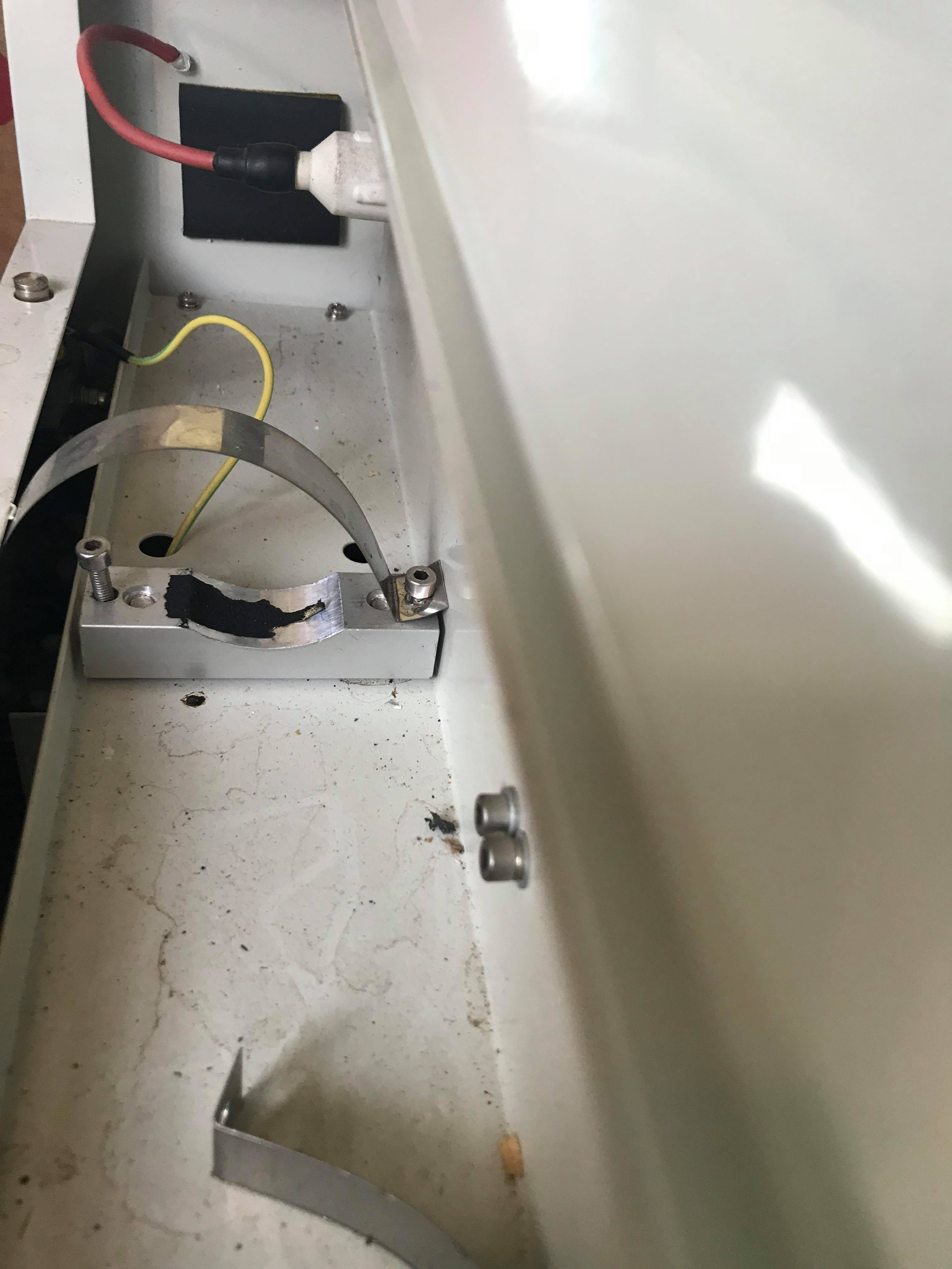
That little rectangular piece is a ceramic terminal block that originally had the tube ground connected. It’s unnecessary, but I’ll leave it in.
More elbow grease needed.

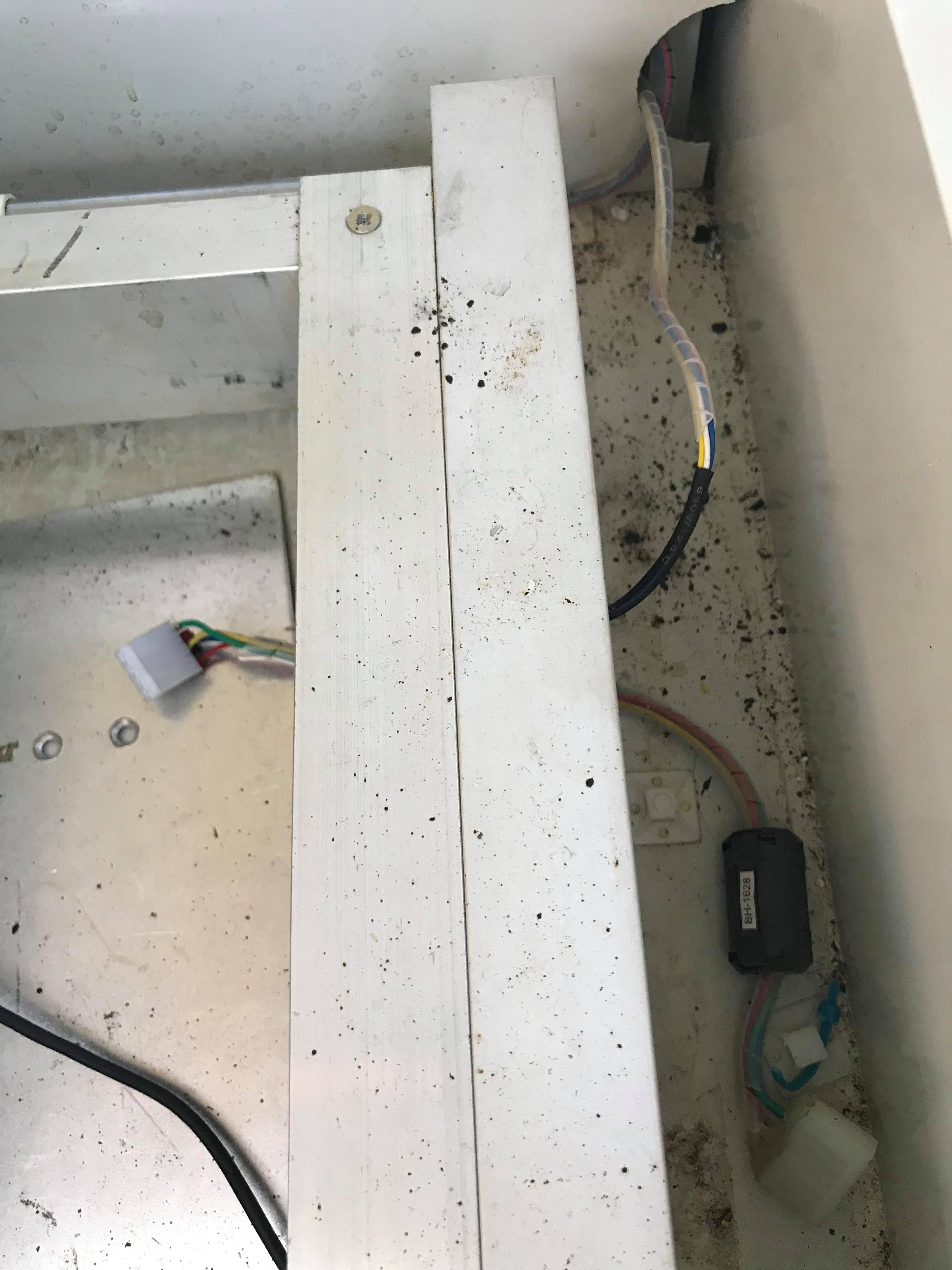


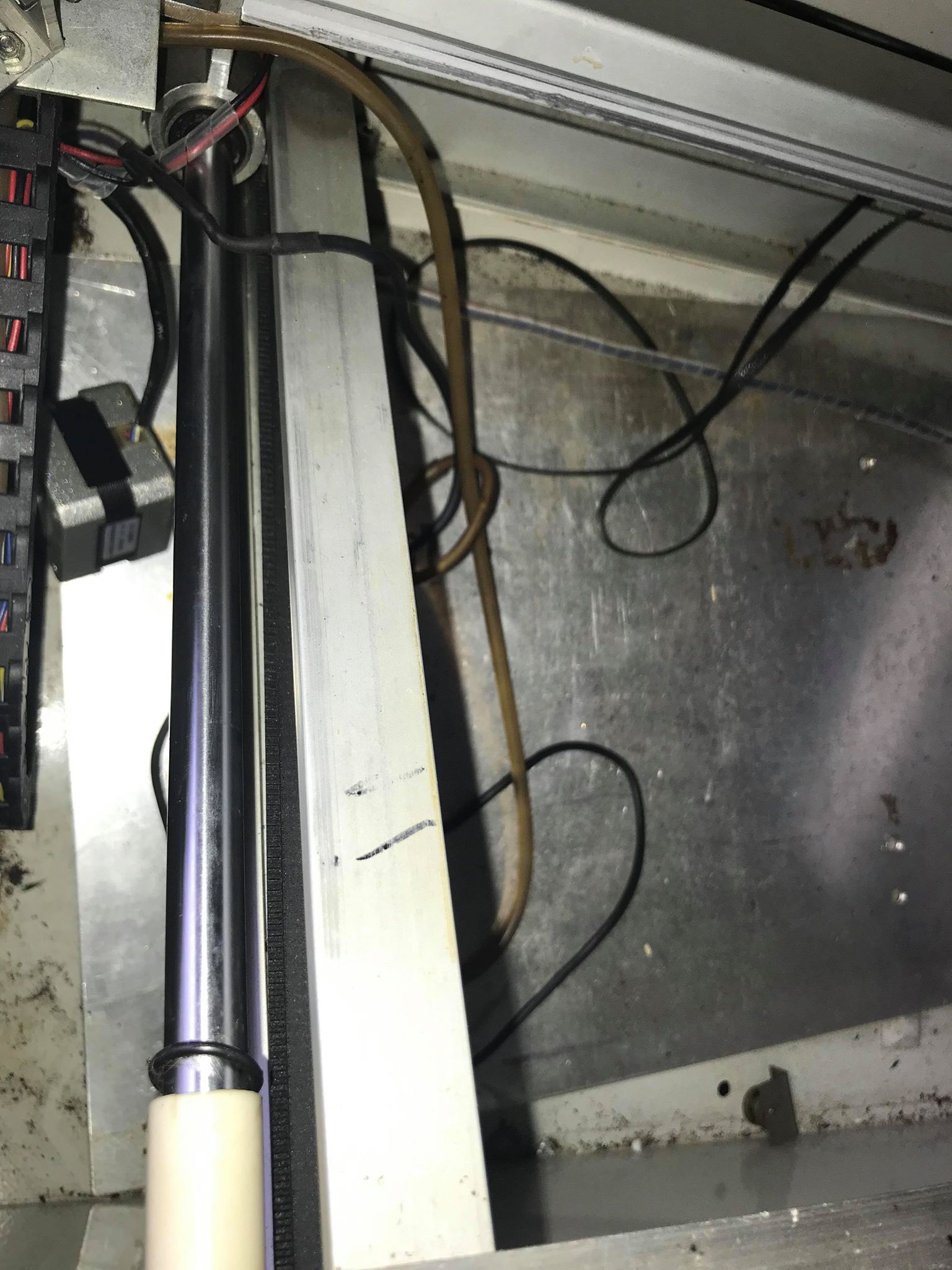
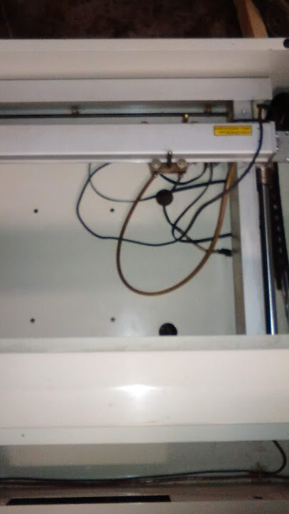
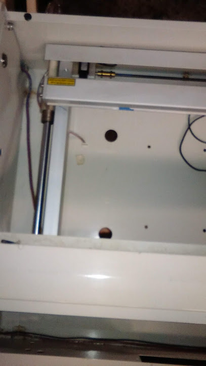
Tube bay. I Need to find something to put around the tube since the original rubber grommets are missing.
This actually looks worse than it is.
Some of the wires were cut. No problem, I’ll get to those.
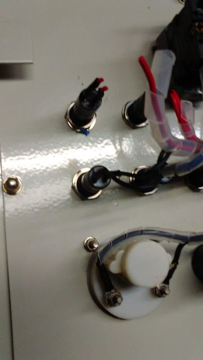
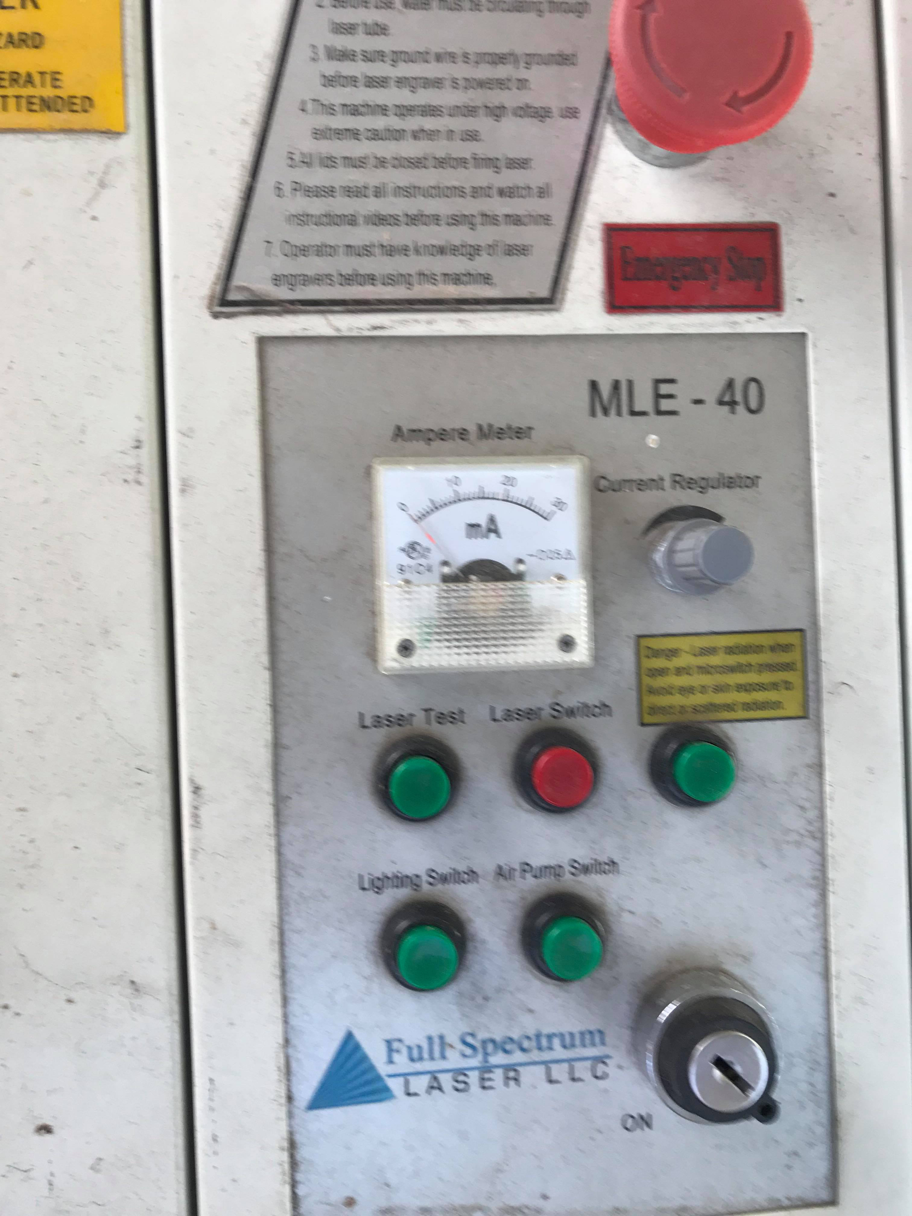
I originally thought someone changed the potentiometer to a multiturn design, but then found out they came standard and were disabled altogether after 2012 to become software controlled. An even more awesome software called LightBurn will be controlling it now!
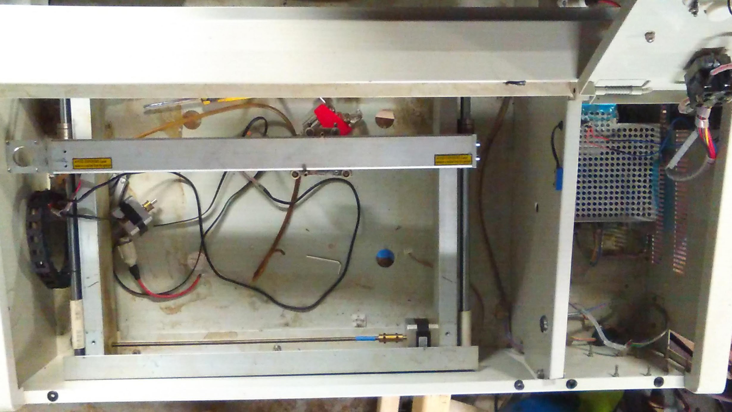
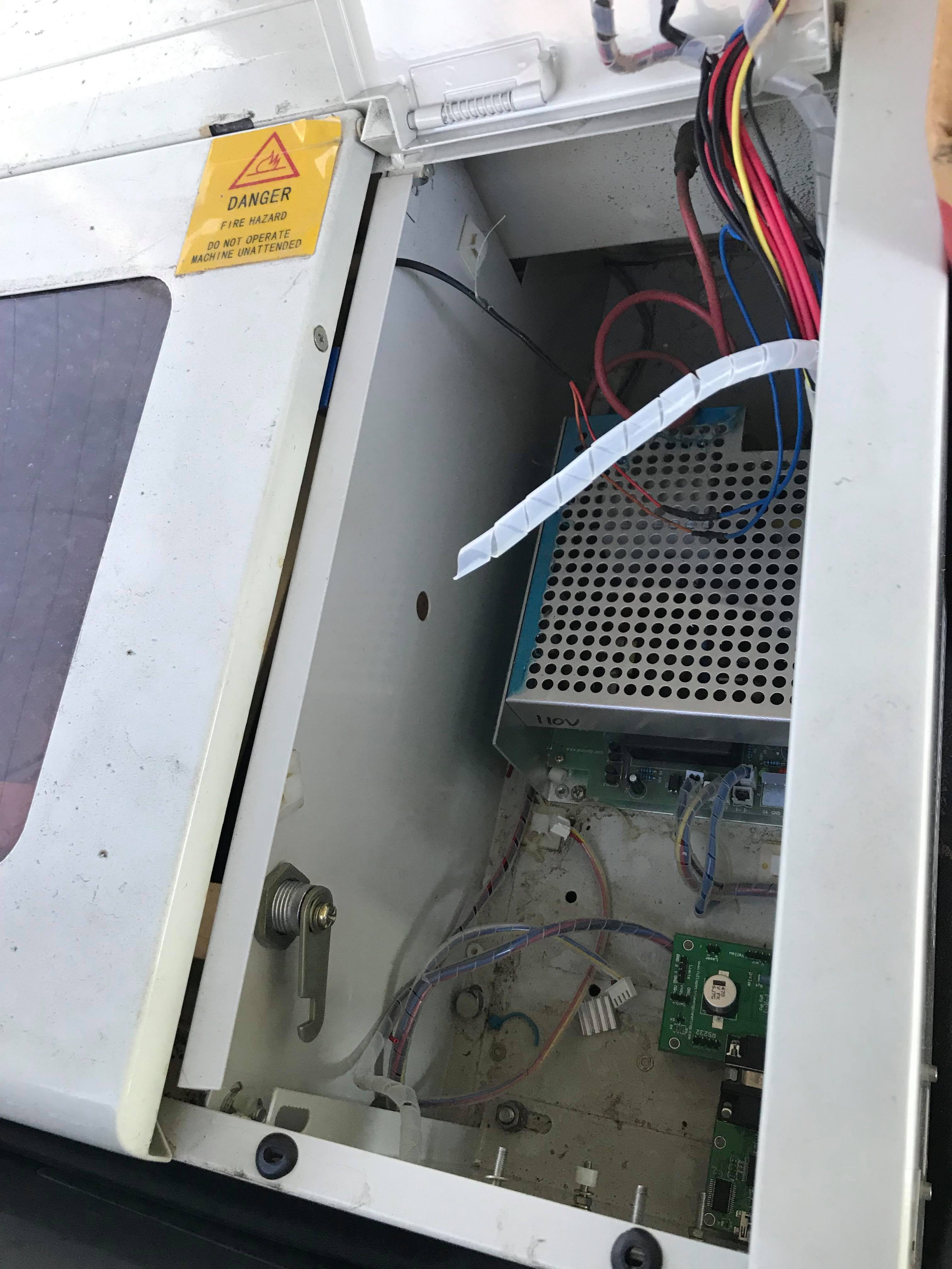
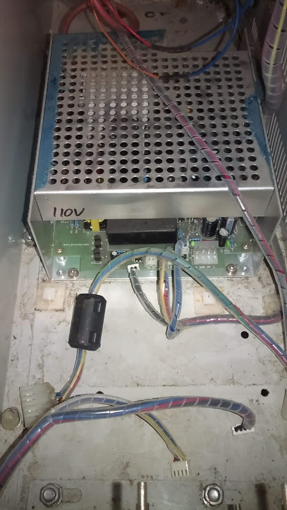
Electronics compartment. I’ve seen worse. ![]()
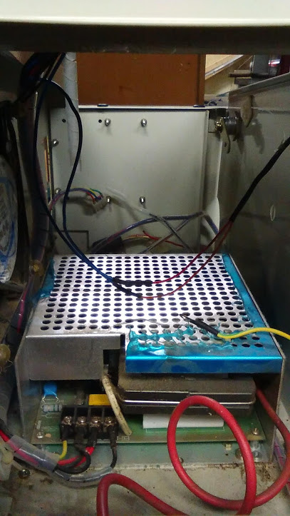
Rear shot of electronics compartment. ![]()
Surprisingly, the power supplies used in these have the same type 2 plugs and would directly connect with a K40 replacement supply.

Starting to clean up fairly well!
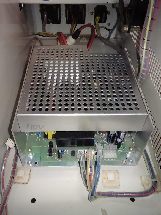
I have a good bit of it disassembled here because I want to go through each part to make sure anything needing replaced isn’t missed. The only thing actually bolted down when I got it was the power supply.
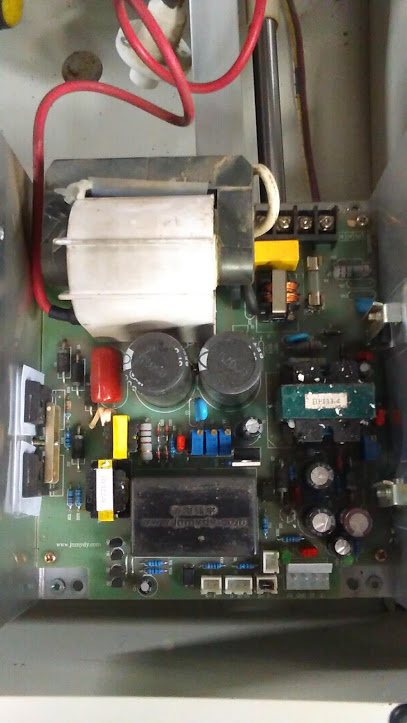
Took a look inside the power supply to make sure some things didn’t get inside during shipping since there were some loose screws and washers. Good thing I did, there was a washer stuck inside.
Interesting internals. Slightly better quality than the stock K40 supplies.
This is where the Cohesion3D is going.
Electronics compartment is definitely starting to look better!
Gantry is bolted in. Everything is square, the higher quality (than a K40) aluminum gantry held its own during shipping.

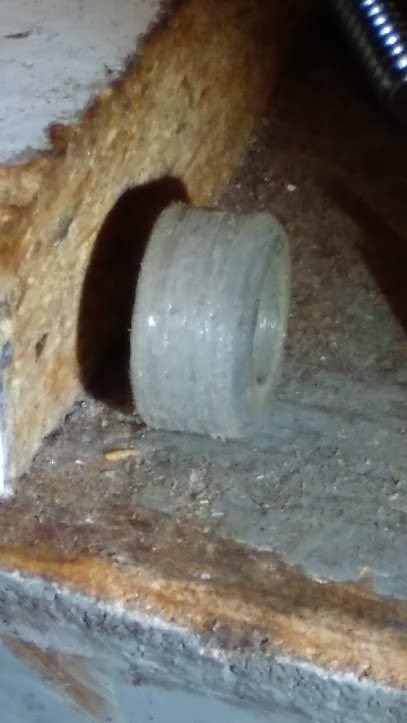
One problem the machine had was the carriage wheels. The two on the rear of the carriage were in bad shape and had been replaced with 3D printed pieces that didn’t quite work out.
Here’s one I tried cleaning up by putting it on a drill as a sort of makeshift lathe, but even with it spinning and using sandpaper+steel wool, this is the best it would do.
So I had no choice but to order new ones. Cohesion3D now sells these in 4 piece kits, BTW.
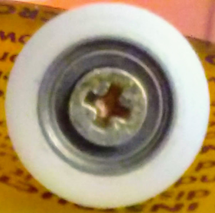
Looks good!
Shot with both sides.
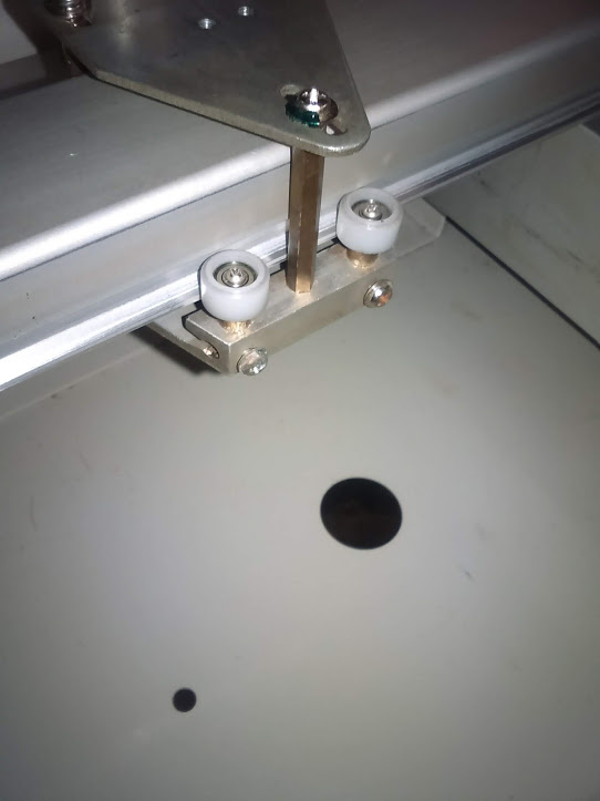
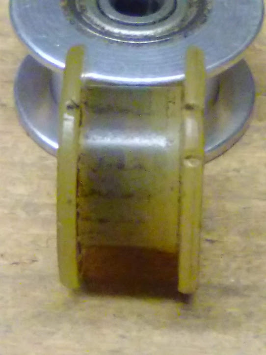
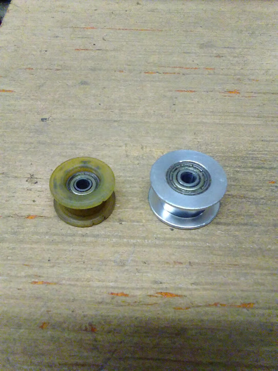
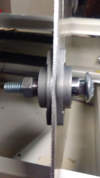
The next problem was the idler wheel for the X axis. It had an intermittent grabbing feeling while moving the head carriage back and forth and my first thought was that it perhaps had a bad bearing, but after swapping bearings, there was no change. This lead me to believe the plastic part itself became misshaped and I had a larger aluminum pulley that I planned on using sometime in the future with a DIY build using GT2 belt, so I put it to use. it is working fine and the head carriage now moves smoothly without any grabbing whatsoever.
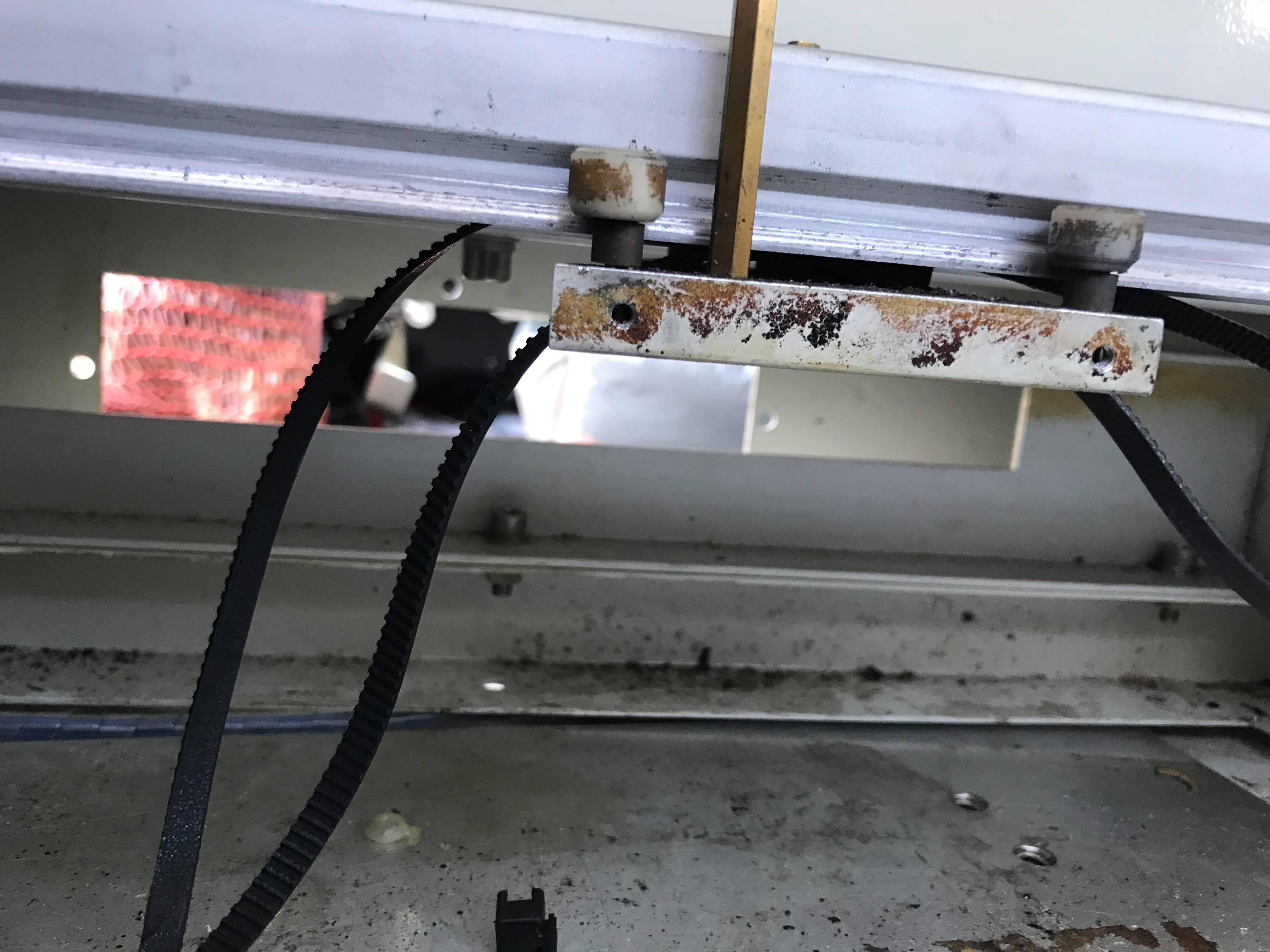
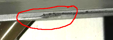
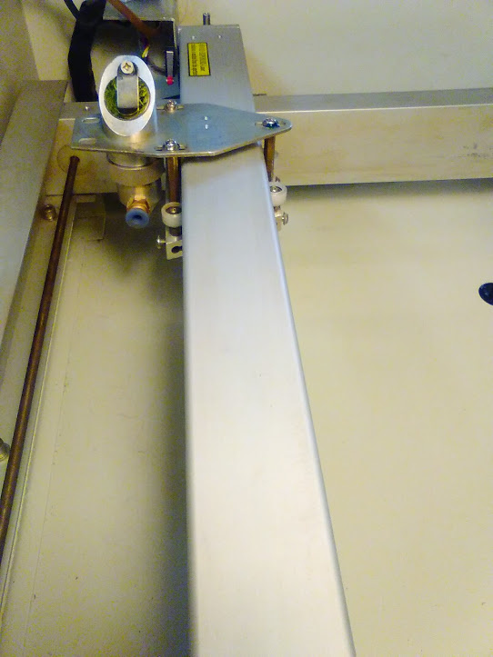
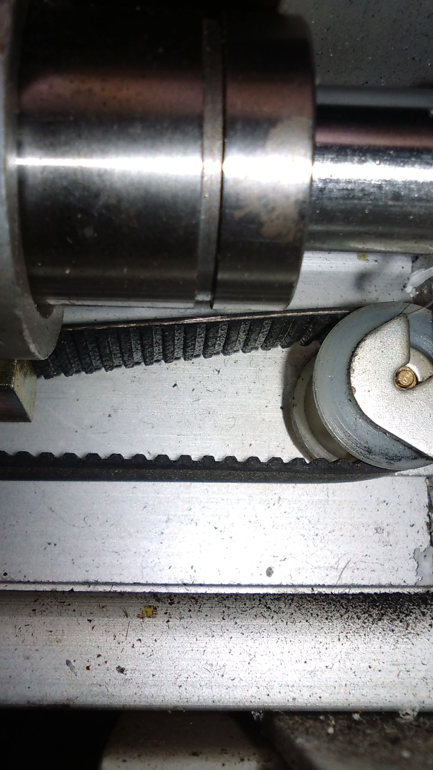
It appears that someone changed the belt to a slightly smaller K40 belt. You can clearly see where the smaller belt left its mark. I’m going to completely eradicate the MXL setup and switch to GT2 pulleys and belts. 6mm for the X and dual 10mm belts for the Y.
Slightly larger diameter than stock, both are 6mm.
That MXL Y axis belt looks terrible.
This is its replacement! GT2
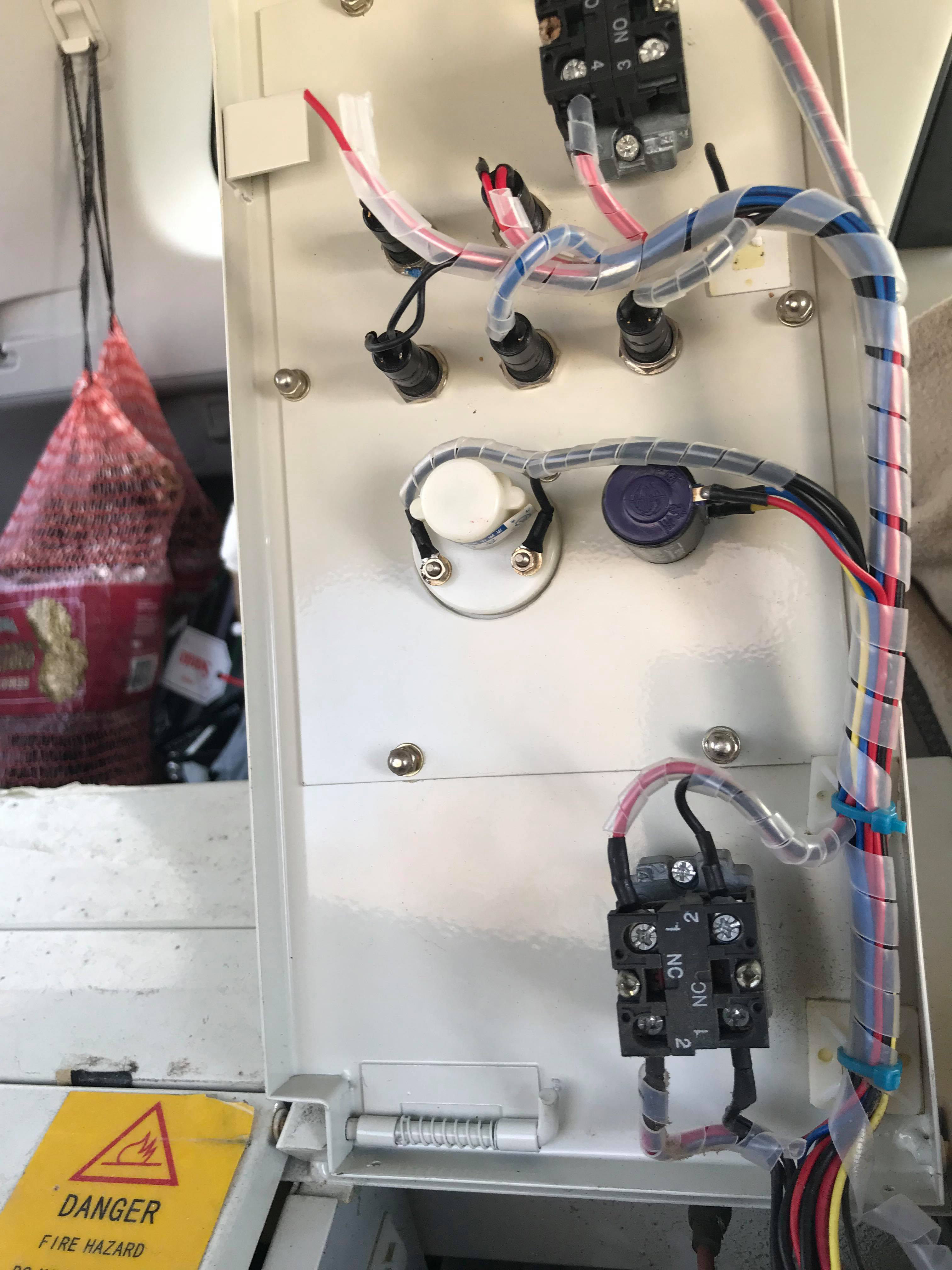
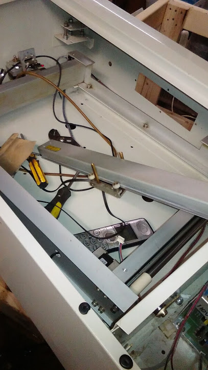
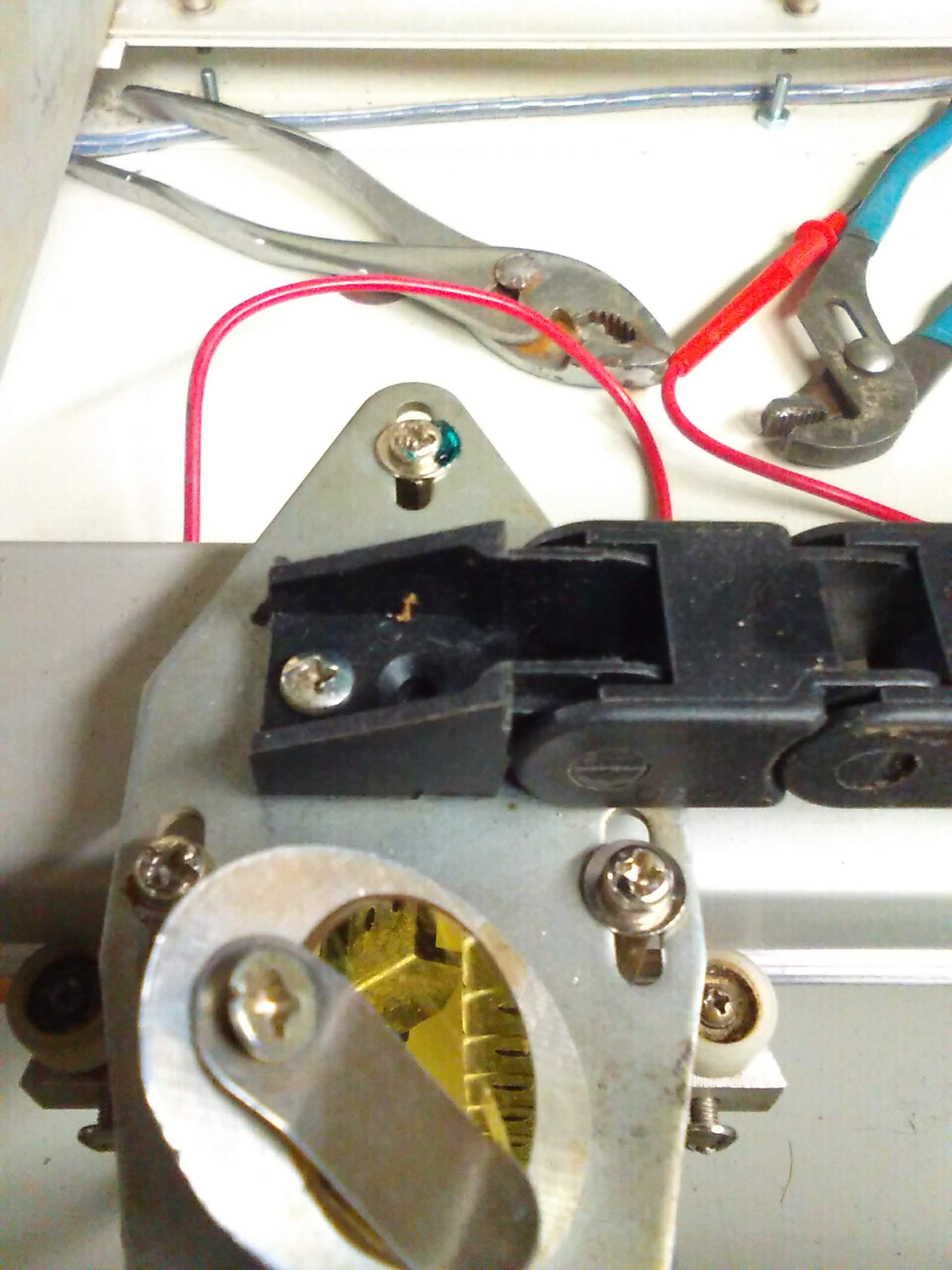
Some people claim I’m never happy with anything I do because I appear to be a perfectionist. Perhaps they’re correct, so I tore the heck back out of it and started over to correct a couple things I wasn’t happy with, like the limit switches. Also sat a couple things inside temporarily, hence the flaring tool.

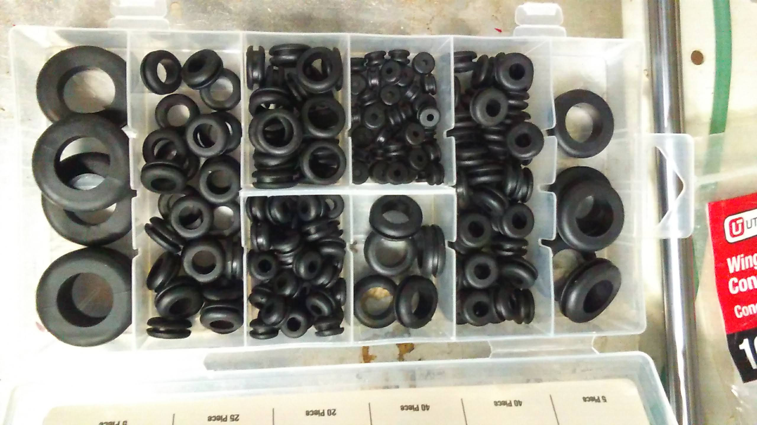
Now that the shock is over, Harbor Freight has rubber grommets fairly cheap, so I picked up some to use on various projects, but I also noticed the frame where the lid comes down has rubber grommets as a sort of shock absorption aid and found it ironic that the grommet kit contained the same size, so I yanked out the old, squished grommets and replaced them with the nice, new and fluffy ones. ![]()
Out with the old
In with the new, fluffy variety.

When I changed the Y belts, I had to remove the linear rails. I checked the bearings and they were great, no sideways play to be noticed an they glided along the rail smoothly.
That’s gotta go!

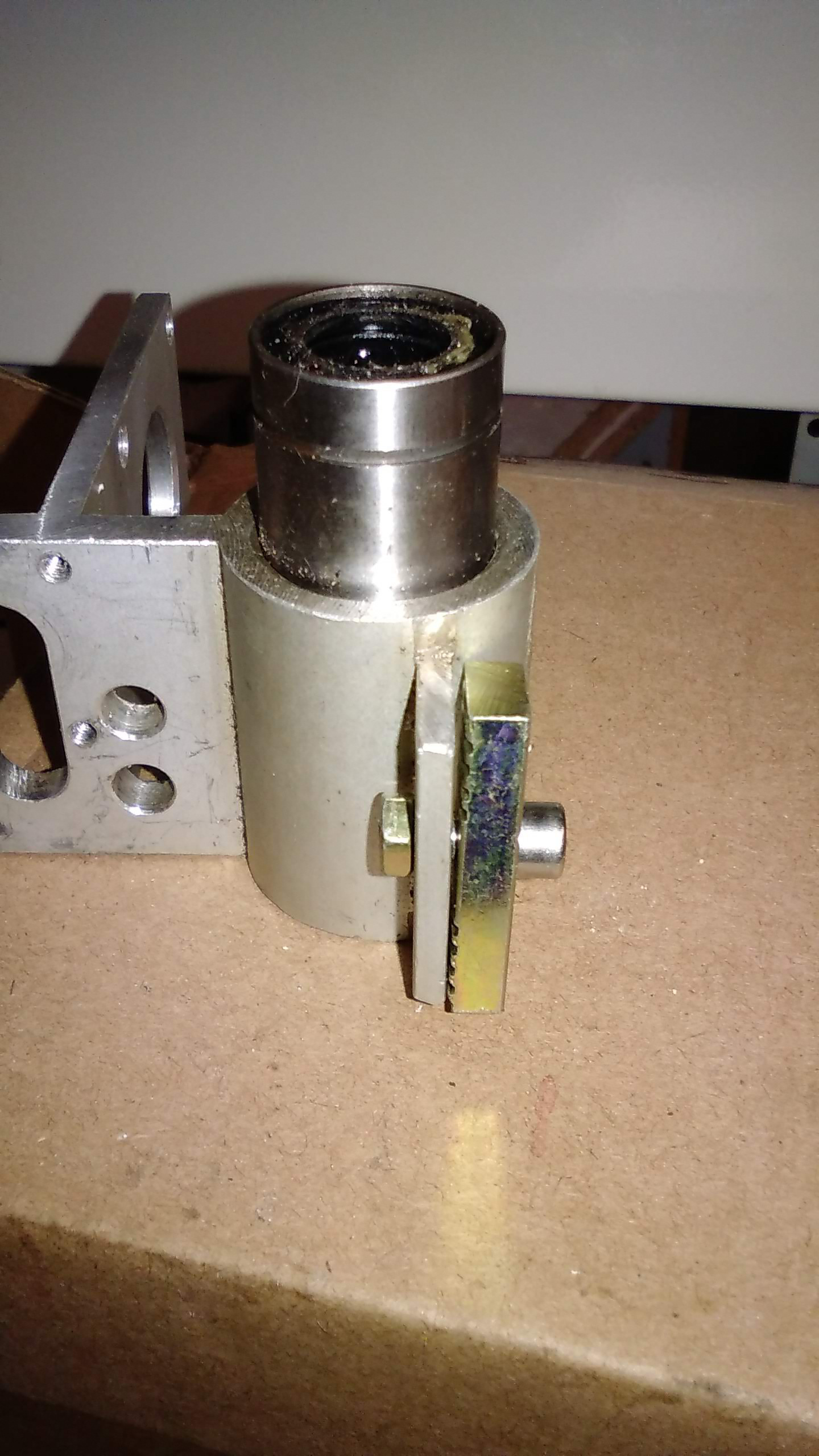
Getting the pulleys off was a challenge since I didn’t have a puller. I figured the easiest way would be to remove the rotor and put it in my arbor press. That would have worked had the magnet not stuck to the side of the press. I didn’t know it happened and it damaged the rotor. I am using more powerful motor for the X rail now.
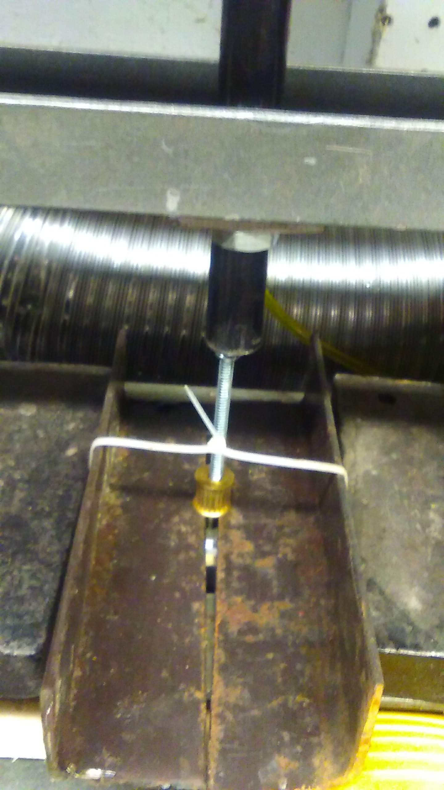
For the second motor, I figured out another way to remove the pulley without removing the rotor by putting it in my hydraulic press and using two pieces of angle iron to hold it in place and a 5mm bolt to push the shaft out. I need to work on getting a puller! This worked great with no damage!
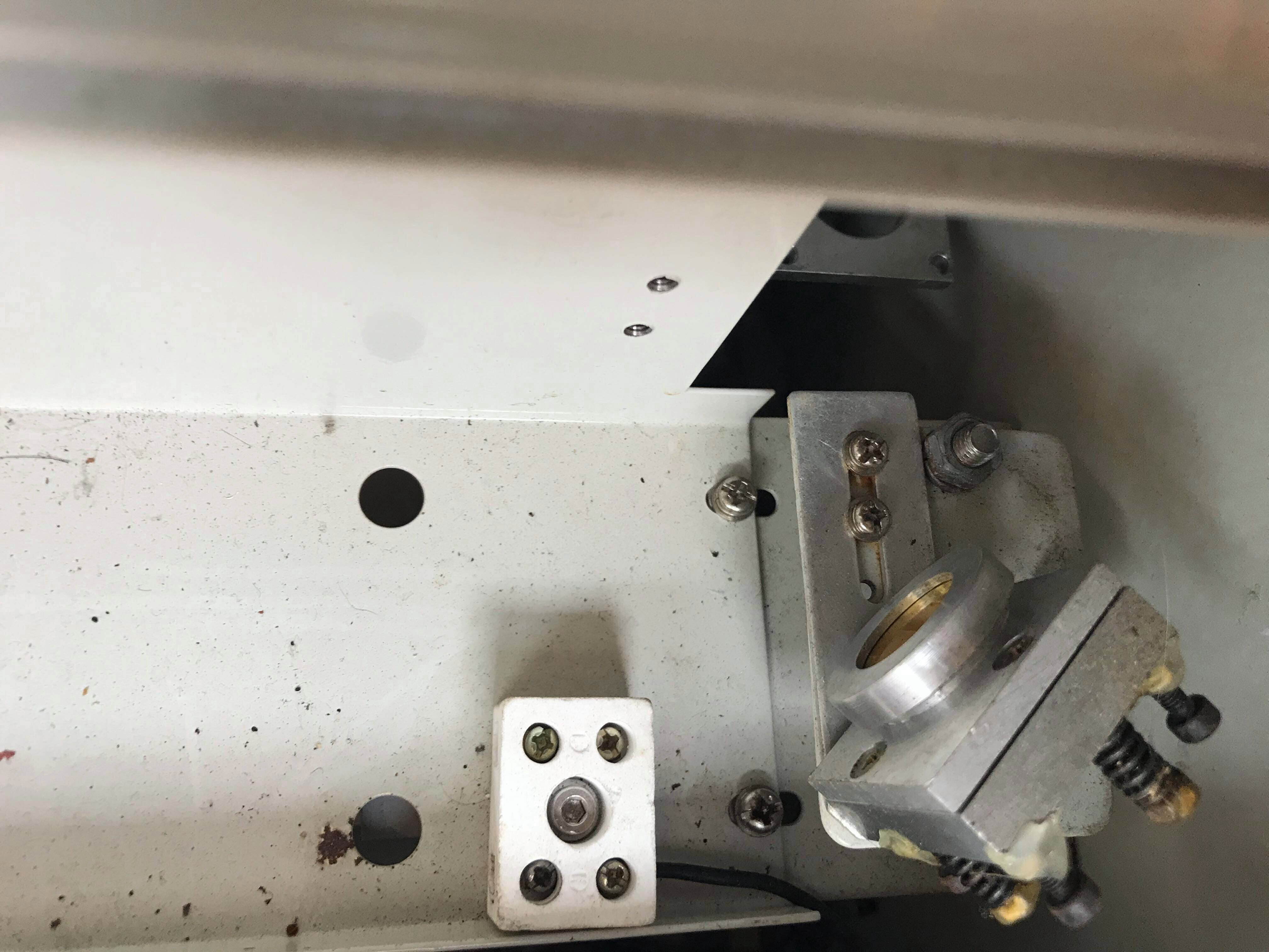
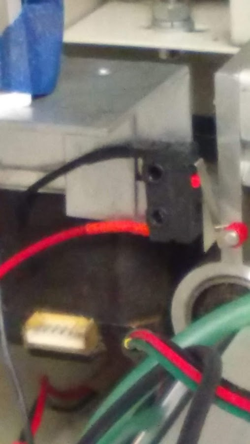
I not only wanted to redo the soldering on the limit switches, I wanted to reposition the X switch because it’s under the rail and doesn’t allow the carriage to move as far as it can while still having cut space, so I decided I was going to relocate it.
The X-Rail goes over this and I realize they were probably just trying to hide it, but that wasn’t the way to go about it. I had a different idea that would give me over 15" of cut space and still limit the carriage without going out of the cut area.
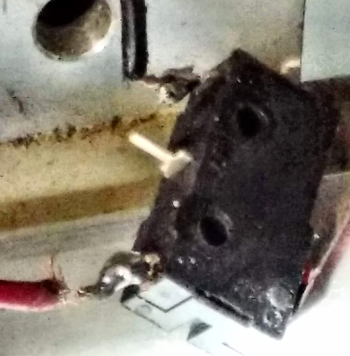
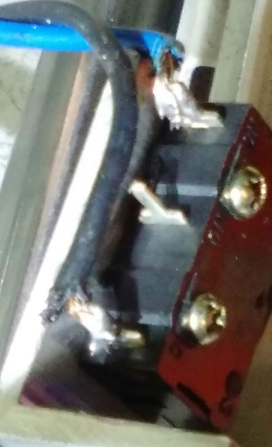
This switch has seen better days. Not to worry, I can solder. Also want to clip out that pesky center pin.
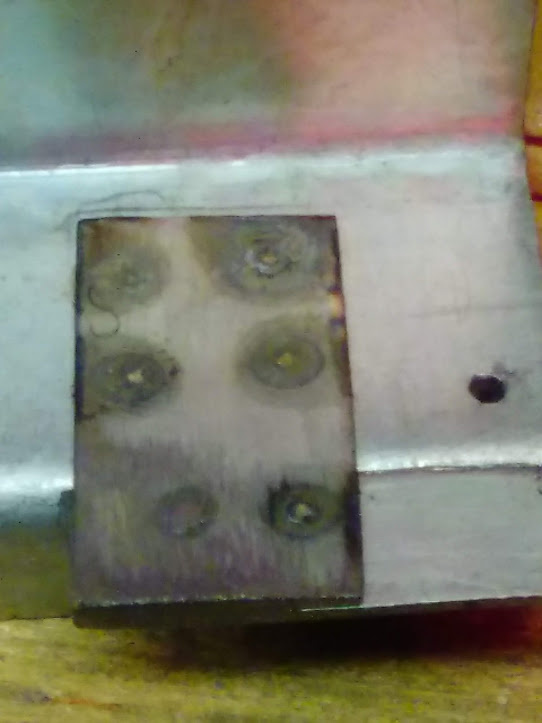
I made a spot welder a couple years ago using a microwave oven transformer. (don’t try this at home, kids) I never really got to use it, but relocating the endstop switch finally gave me a reason to!
It’s a terrible looking thing, but gets the job done!
Getting back to the limit switches, the ones I removed to resolder are not the originals. The previous owner thought they were bad and replaced them, so I tested these ones with the continuity function on my multimeter just to be sure they’re ok and they tested good. If you suspect your switches are bad, the mechanical switches are normally closed and can be tested with a meter. If you are reading this and have a K40 with optical limits, here’s a guide to test them:
 LaserGods.com – 10 Aug 18
Testing K40 Endstops With LightBurn - LaserGods.com
Sometimes endstops can cause some hard-to-find issues. If you have a Cohesion3D or other Smoothie based controller you can troubleshoot your endstops from within the LightBurn console. There are a few prerequisites for this to work. Your controller…
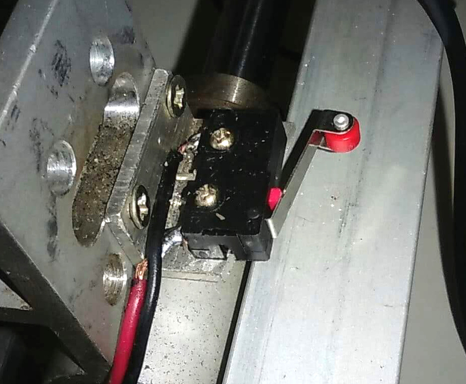
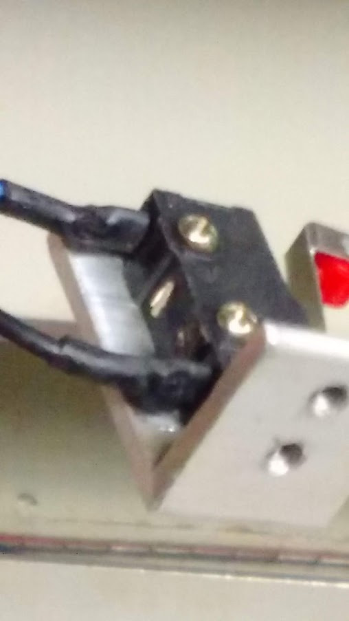
My solder job looks slightly better than original, although I could have gone a little closer on the bottom wire.
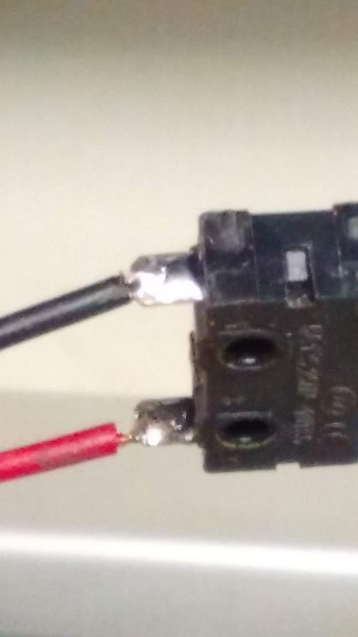
Let’s slide the heat shrink on, use the heat gun and attach it! I have this thing about using longer than needed heat shrink tubing. Won’t hurt anything.
Looks good! Those wires will be straight out to the left when I’m finished.
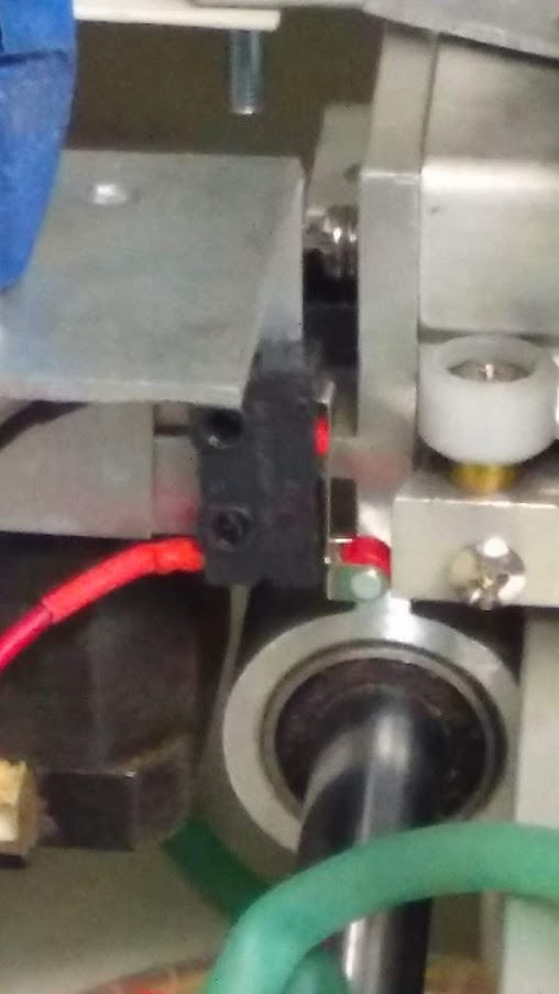
It triggers just before this, but gives a good idea of how well it’s mounted. I now have just over 15" cut area on the X.
Now on to the Y switch! Not quite as bad as the X.

Yay, I actually used shorter heat shrink tubing!
Since the original drag-chain and bracket for the X-Rail were cannibalized for use on the previous owner’s K40, I had to come up with my own mount, so I thought fair play was in order and decided to cannibalize something from my K40. Many things I fix are accomplished using leftover parts from some other project, or just something I have that I don’t really need anymore.

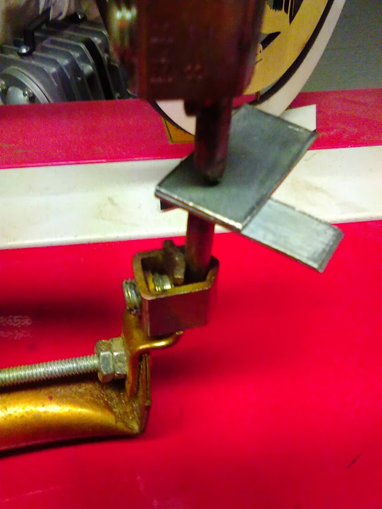
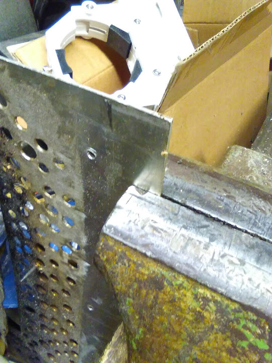
I made my own adjustable Z for the K40 using perforated carbon steel and punk rock spikes (will also do that to this one) and certainly had no use for this thing anymore, so I thought I would cut a piece off of and make my own bracket from an area I hadn’t drilled holes in.
My phone blitzed out on me and some photos are missing, but this should be sufficient.
Clamped in the vise and marked where I want to cut.
MISSING CUT AND BEND PROCESS PHOTOS
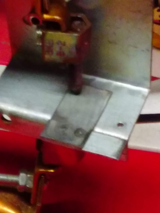
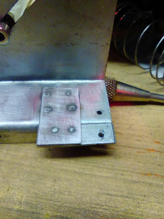
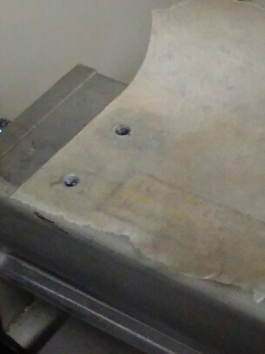
Using the “tape method” to get the hole spacing I need for drilling into the aluminum I cut off. Unfortunately, I don’t have the photos of the cut piece before and during the process of drilling and bending.
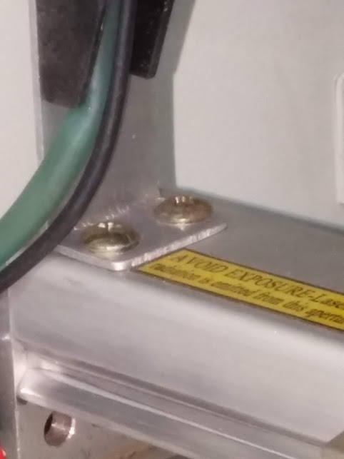
Perfect! There are two different types of screws (temporarily) because the threads in the rail are damaged, but I’ll fix that before the final mounting. Just need to drill the holes for the drag chain, trim it, clean it and it’s ready to go!
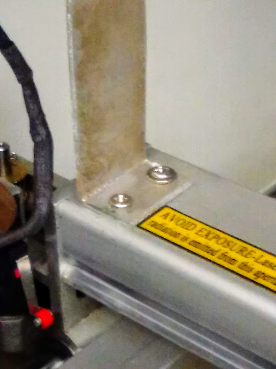
Need to get some tapered screws.
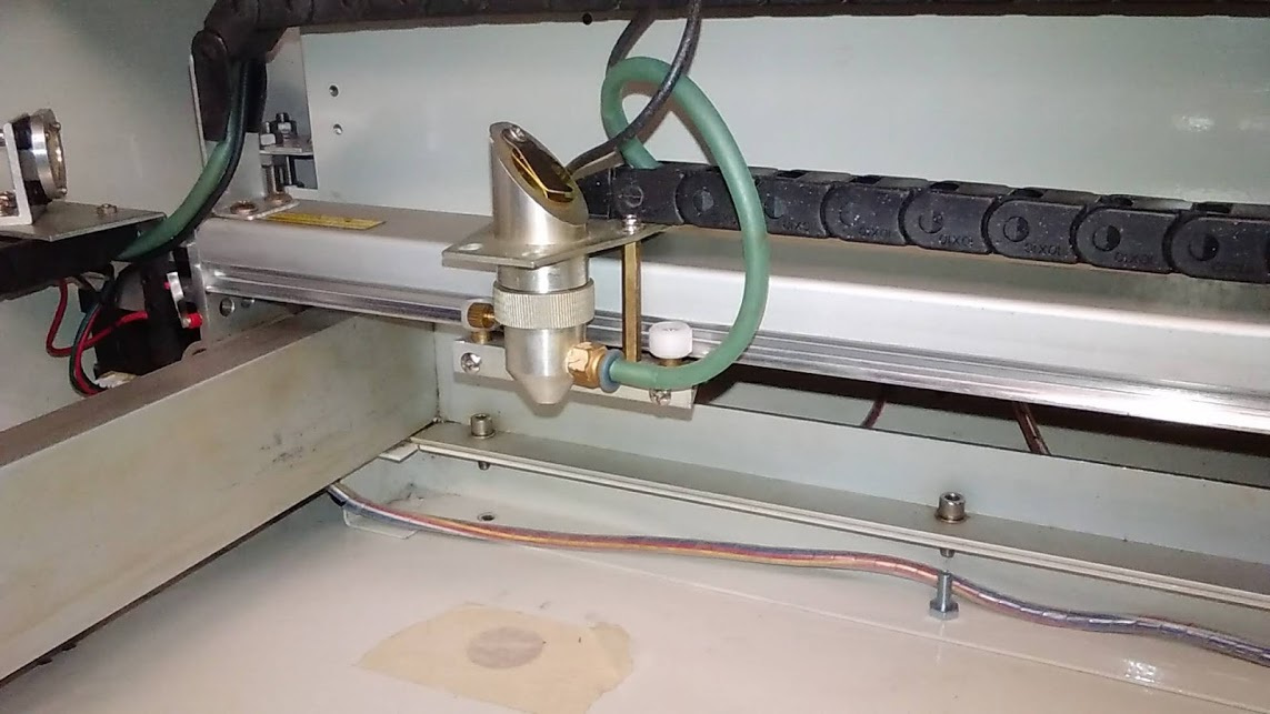
NOTE: The mirror in the head was already like that when I got it.
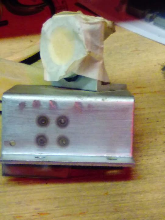
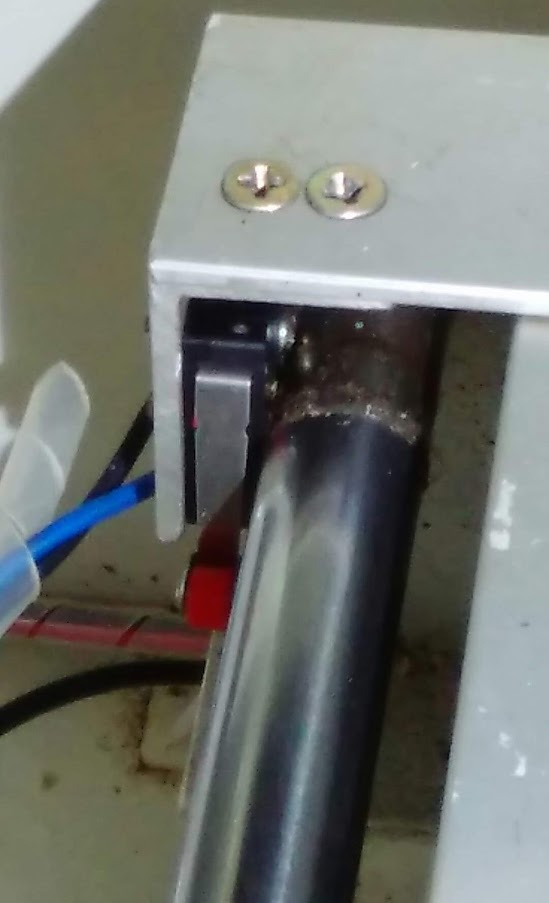
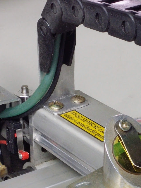
Here it is mounted (10x10mm) with a couple larger screws. I left this bracket long for now, but may cut it down after I get my 7x7 drag chain from China that I’ve been waiting on for 60 days. They keep reassuring me China Post has it in transit.
I may put a spring around the hose where it looks to be pinching, or just pull it down a little and see if that takes care of it.
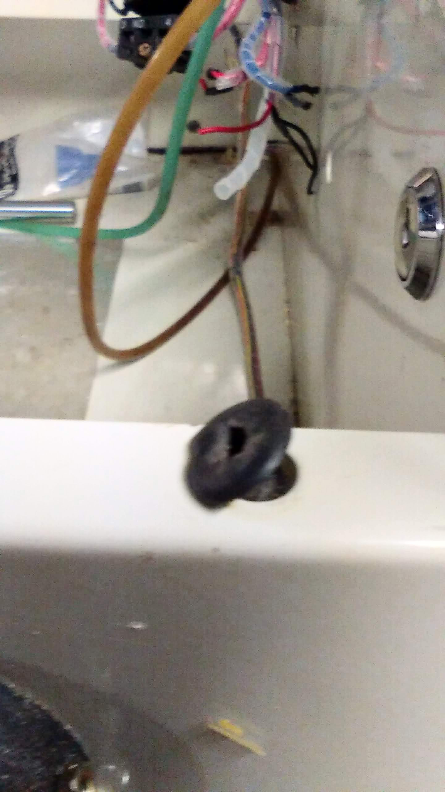
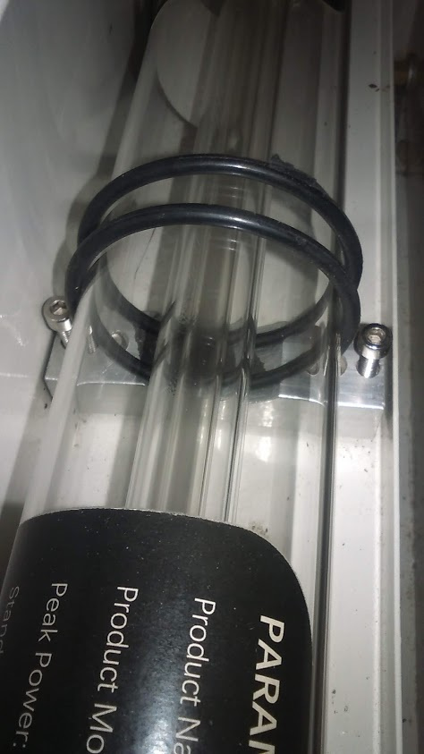
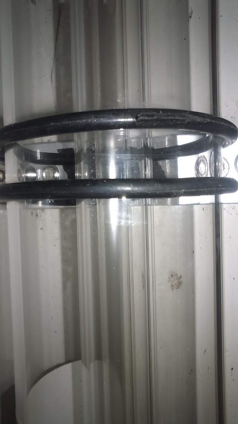
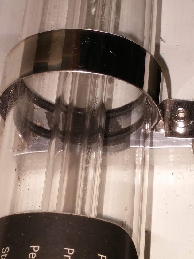
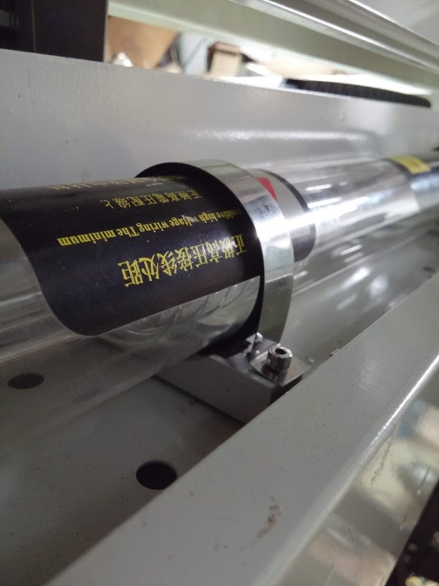
The large rubber grommets didn’t come with the unit and I’m not sure where you would get them in that size, so I thought of something else. I bought an o-ring kit from Harbor Freight for various other projects and the largest size just fit the tube. It’s a simple solution and I didn’t have to buy anything fancy to mount it. There are a lot of rotary setups using large o-rings and I’m going to make a simple one using some from the kit.

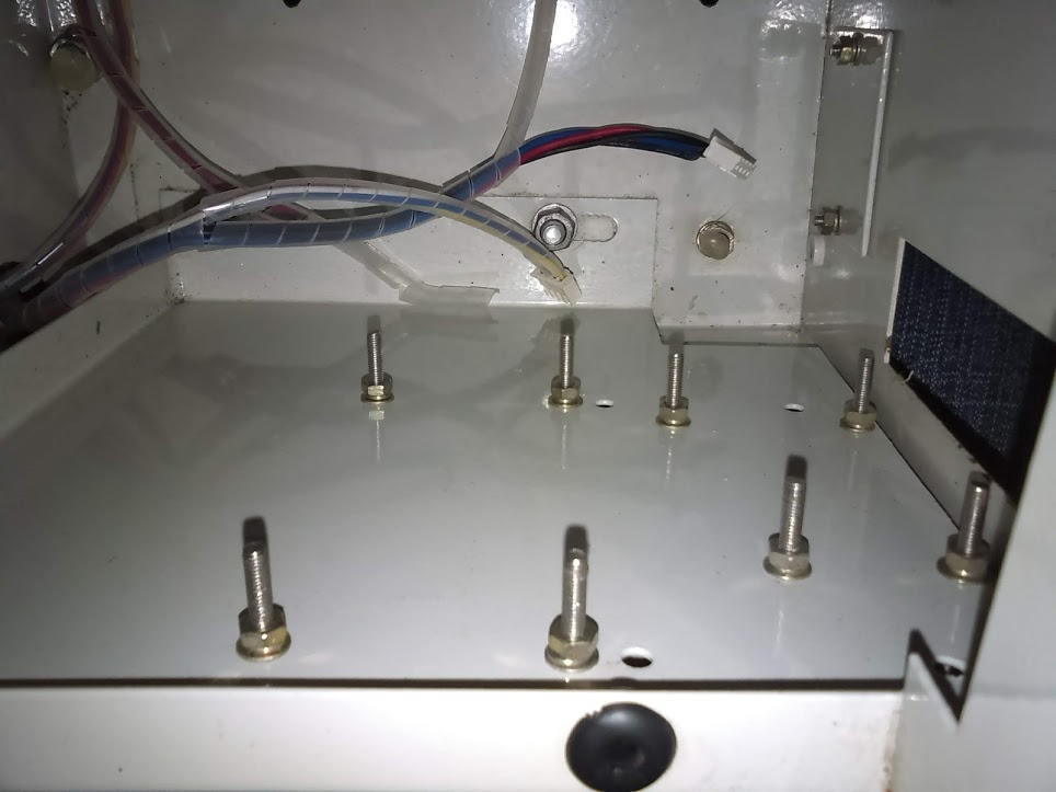
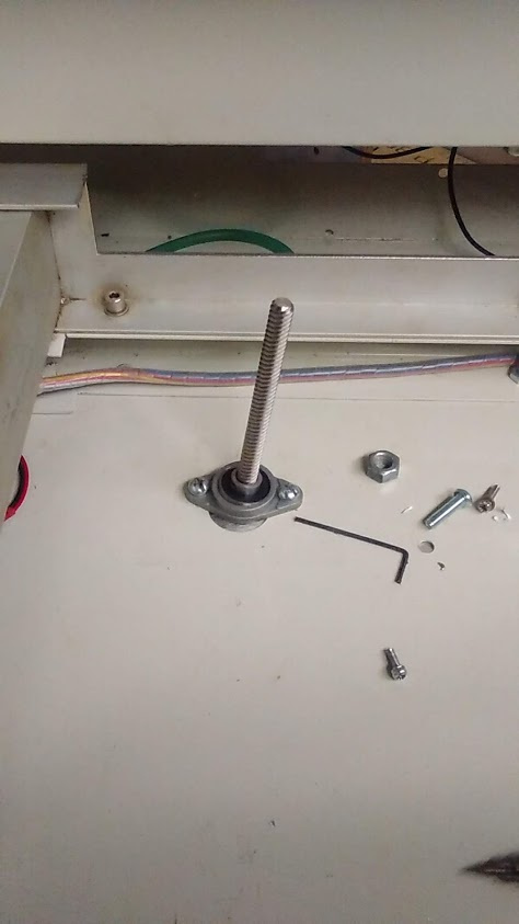
When I created the adjustable Z table for my K40, I used self-adjusting pillow block bearings with one on the top that required drilling into the steel gantry and one on the bottom, which of course required drilling into the floor of the laser. This worked, but I found the top bearing to stick out a little too far and in some instances interfere with the material I was working with. Having a limited working area to begin with, this option was less than desirable.

So how do I make this into a sturdy, self-standing piece that doesn’t flop over once bolted to the floor?
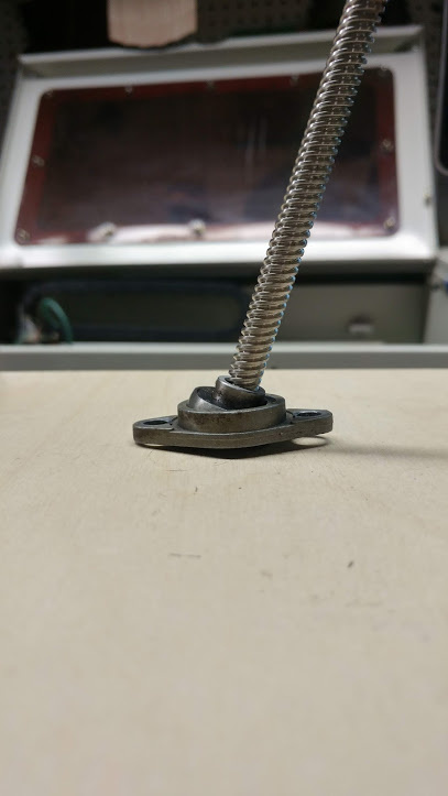
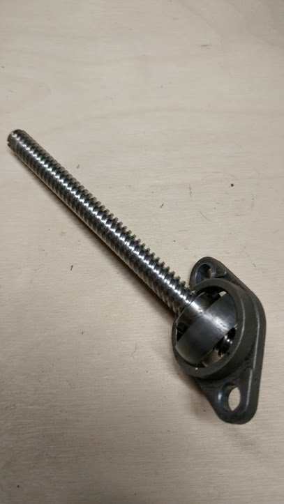
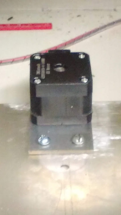
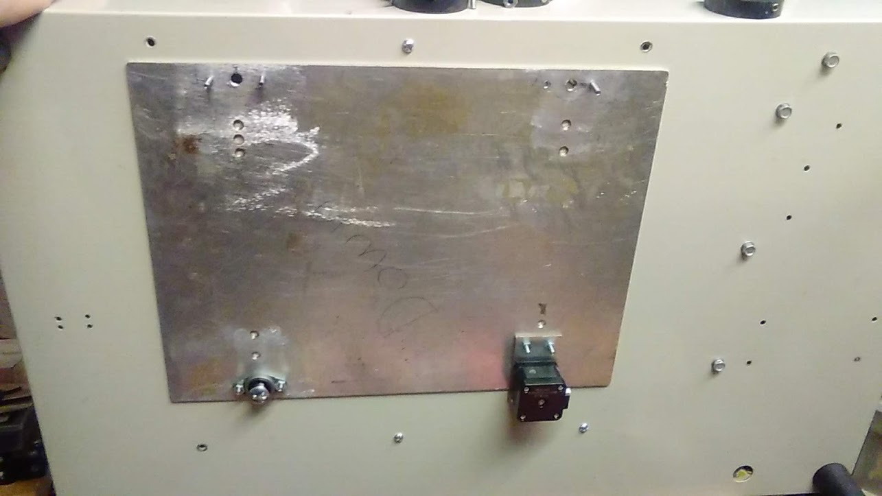
By using two of course! One on each side of the sheet metal which tends to cancel each other out from being able to swivel, while still having the ability to turn freely. I could have probably found another method, but these are only 99 cents each, so why not do it this way if it works? Also, I’m mounting the stepper motor with integrated lead screw on the bottom of the unit in one corner. I’m always finding unconventional ways to do things, but this one is quick and easy.
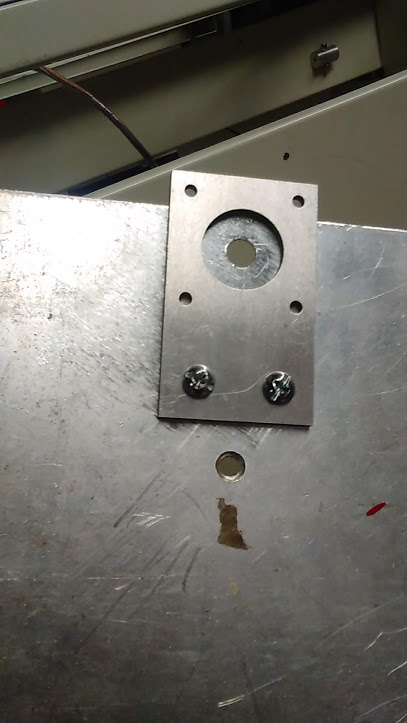
I needed something to help stiffen the bottom a little and one of the aluminum (aluminium to everywhere else in the world) plates was still with the unit, so I’m temporarily utilizing it until I come up with something better.
I wanted to make sure my theory was sound, so I tested this out on my K40 first just to make sure it would hold up; it did.
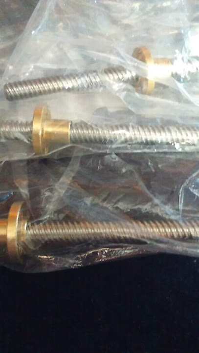
These were only a few bucks on eBay. I don’t have very much money into this. No need to buy an expensive motorized Z when you can make one for less than $60.
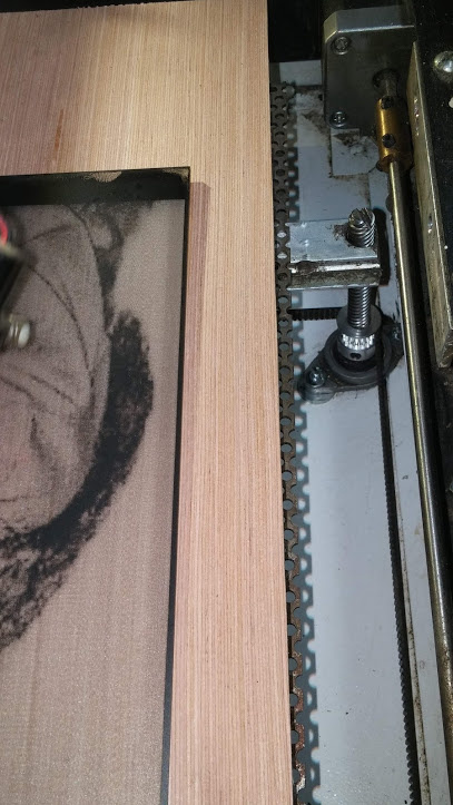
The stepper motor is actually being moved to the front so I don’t have to run the wires as far.
I now just need to install the belt and stick my perforated steel spiked table in place. Check back to this thread, I may edit and insert that part once I have the belt.
LaserBoard installation:
Installing the Cohesion3D LaserBoard into a Full Spectrum MLE-40 4th Gen Laser is easier than you may think. There were two different controllers and three different configurations used in this model and I’ll cover each one as I go.
You’ll need a small flat screwdriver for attaching some wires.
This is the first controller used in the early models and comes in two pieces with connectors that plug directly into the board. You will only be able to plug the stepper motors directly into the LaserBoard, the rest will need to be connected with the screw terminals.
IF YOU HAVE THIS CONTROLLER, PROCEED TO: LIMIT SWITCHES

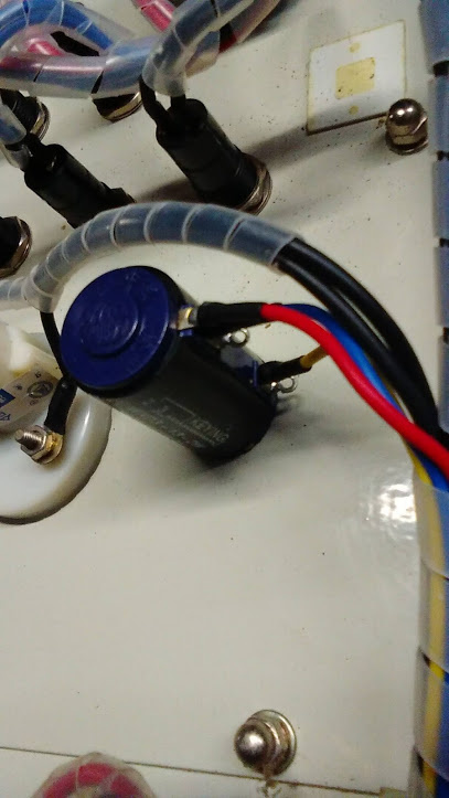
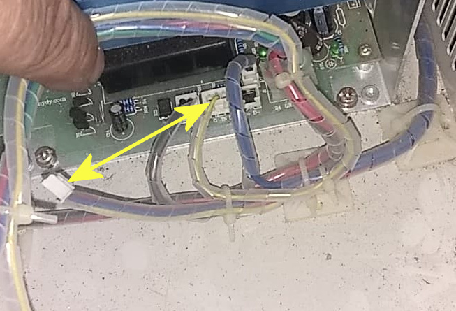
This is the second controller version with two possible configurations, one with the current controlled by the dial on the panel and one with the current controlled by software. They generally left the potentiometer mounted in these units with the cable unplugged and laying on the bottom near the laser power supply. All you’ll need to do is unplug the wire going to your old board and plug the one laying free in its place, as shown below. You’ll use the dial to set your maximum safe current, which is usually around 15mA to 16mA and LightBurn will control 0-100% of your set limit.
Photo courtesy of Chris Cecchini.
Simply swap these two plugs and set the current to 15mA.
Photo courtesy of Jeff Gray.
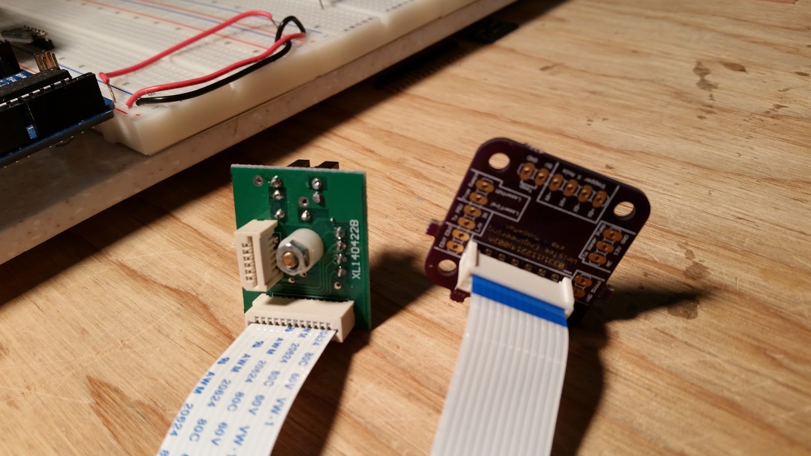
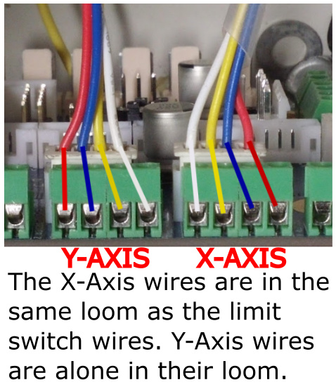
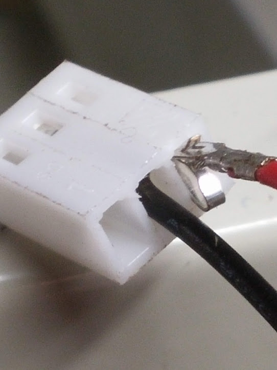
The connector ends on the wires are cut off on this model controller, but it’s no problem for the LaserBoard since it has screw terminals for the stepper motor wires and laser firing control.
Make sure to note the X and Y cables and place the wires accordingly.
LIMIT SWITCHES:
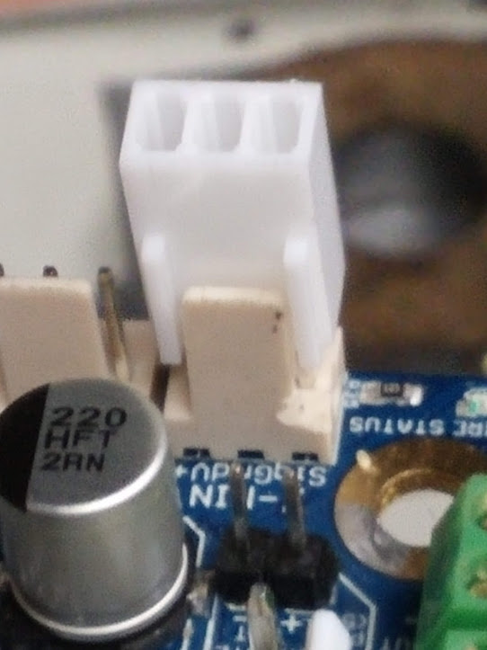
In order to properly mount your limit switch wires, you’ll need to purchase inexpensive 3 pin Molex KK connector ends. These are very easy to install and can be purchased at the Cohesion3D online store.
Connector Pack for Cohesion3D LaserBoard - Cohesion3D
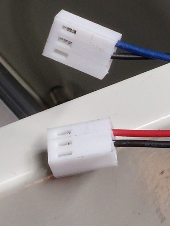
Your limit switch wires are going to be the thicker red, blue and two black pieces all in the same wire loom. The black wires should go to the center pins, which is ground and the colored wires will go to the signal, NOT the V+. The red wire is for your X-Axis switch and the blue wire is for your Y-Axis switch. These switches are normally closed, and if you would like to pair them, you can use a meter to check continuity. When the switch is triggered, the circuit becomes open and that’s what signals the LaserBoard that it’s in the homed position.
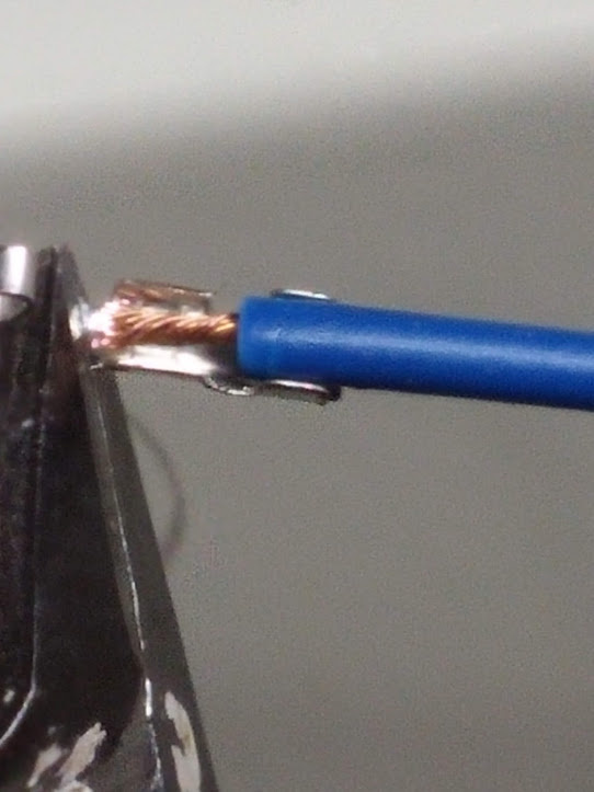
I recommend using a multimeter to pair the wires so any future troubleshooting will be smoother, but is not necessary if you place the black wires in the center pins (ground) on both plugs since the grounds are all tied in. You’ll need to strip the ends of the wires, crimp them in place and then insert them into the plug. Note the position of the clip going into the plug.
Match the size to crimp.
Carefully insert them into the plug housing. Make sure to place them exactly as I have them here.

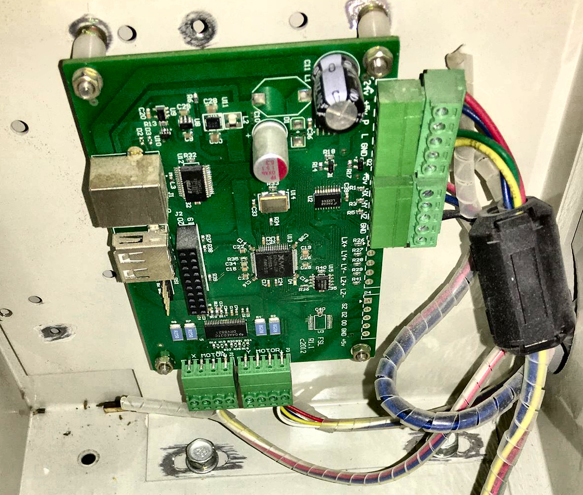
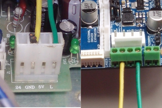
The Cohesion3D LaserBoard comes with a high quality (UL Listed) power supply that eliminates the 24v and 5v requirement from the laser power supply and requires only two wires, the laser fire control and ground. You can remove the 24v and 5v wires altogether as shown or you can use them for your lighting and diode pointer if your unit has one.
Do not attempt to utilize any power from the LaserBoard except otherwise noted in the LaserBoard documentation on "Air Assist Control."LaserBoard Air Assist Control
Connecting anything else can damage it.
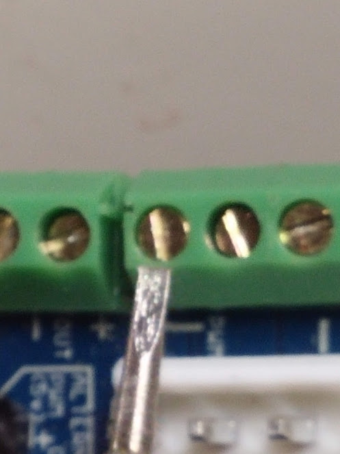
The only two wires needed for controlling the firing. L to the screw terminal shown, which is marked “PWM” on mine (for pulse width modulation power control) and the ground.
Using the 5v out on laser power supply to power the diode pointer is perfectly acceptable since that was the default setup, but there is no longer a need for these wires to connect into the controller and caution is advised to keep them isolated from shorting. The black wires were already cut from my ground, but you’ll need them if you choose to use the laser power supply for lighting or the diode pointer.
I used one existing hole, then marked and drilled the other three.
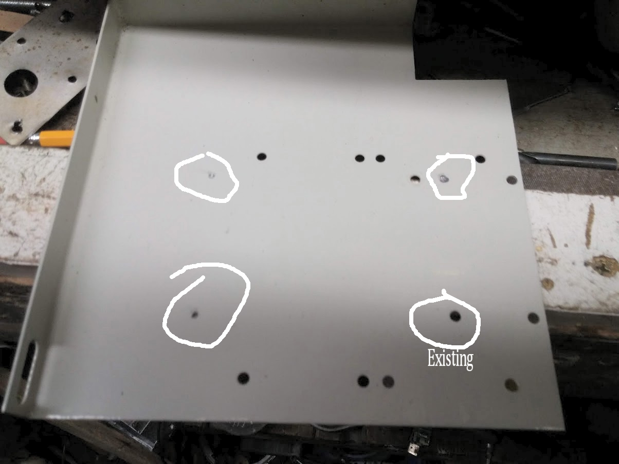
Here it is installed.

The control panel shown in the video is a draft. I’m not going to show the process of cutting the panel since it’s self explanatory, but basically, all I did was use two seperate pieces of acrylic. Top layer is transparent blue and bottom layer is plain acrylic that I painted with primer and then engraved. Illuminating the electronics compartment does the job.
I have a couple of 12v led COB lights in series that are utilizing the LPSU’s 24 volt line with one placed on each side in the electronics compartment and it works great!
Here’s some video of it in operation. Note that this panel is considered a draft because I need to redo it on thinner material, which is why there are aberrations, but I hope to have them eliminated with the final cut.
Okay, here I’m running at 200mm/s. Panel isn’t too clear in this shot, possibly focus.
[Full Spectrum MLE-40 in operation after restoration]

Cutting process, it’s doing great!
[Full Spectrum MLE-40 restoration in operation.]

HERE WE GO, BABY!
I did some configuration tweaking and was blasting at 550mm/s! I started at 600mm/s next to this one, (as you can see) but the acceleration was too much, causing it to jump teeth, so I reduced it to 550. I will probably lower the acceleration a little at a time (when I have the time) to get optimal settings because I had it cranked to 10,000 and I think that’s a little much. lol My original goal was go get 500mm/s and I surpassed that. I won’t run it at this speed all the time because it’s pretty hard on the moving parts, I just wanted to see if it could; it can! ![]()
[Cohesion3D LaserBoard speed test using GRBL-LPC at 550mm/s]

I currently have my LightObject nose cone on it (compatible, go figure) because it has a smaller hole and concentrates the air better. Sorry about the vertical shots, I keep forgetting to turn my phone sideways.


