For me cooling your K40 laser is one of the most important modifications you can make.
It’s obvious the cooling provided with the K40 is a joke. It sort of works but should it fail you may not know and it’s going to kill you tube or at the very least kill some serious life time out it. The first upgrade I did was change the cooling method. I didn’t want to spend 500 to 600 bucks for a electric cooler but I still wanted a reliable system I could monitor and not have to worry about.
I also was in a hurry because I had some parts I wanted to engrave so some things are not pretty and all my upgrades were done in a week. I’ll post later on the other upgrades you may see in the pics… if there is an interest.
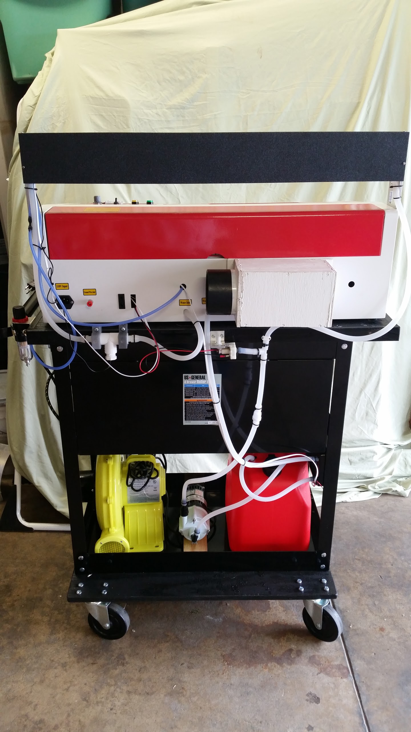
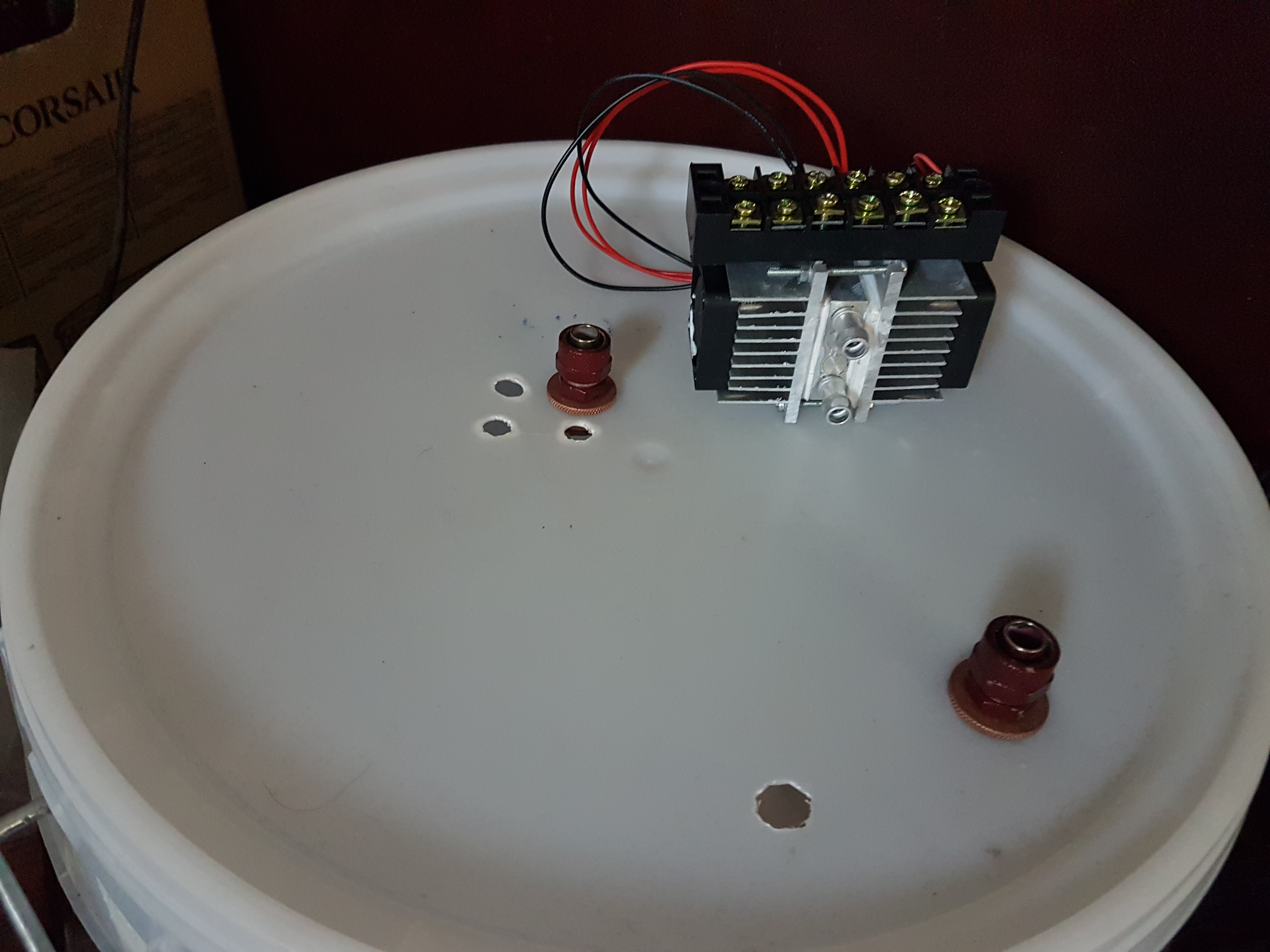
So… to start, Walmart had some 5 gal. plastic gas cans on sale for 12 bucks so I bought one of those for the tank. I drilled two ½ inch holes in the top and inserted the hoses so both are always below the surface and give me the closed system. This way you didn’t have to pump air out of it every time you turned it on. The hose I used (described below) is 5 x 8mm just slightly over ½ inch so it provides a nice seal.
I bought another aquarium water pump to replace the old one but it IMO did not pump enough to give me the flow I wanted. I decided if I was going to do it , do it right and did more searching finding a Little Giant 2-MDQ-SC Water Pump for $108 including shipping.
For coolant I decided to go with a purely deionized water system and use the Tetra Algae Control based on Don’s testing and postings.
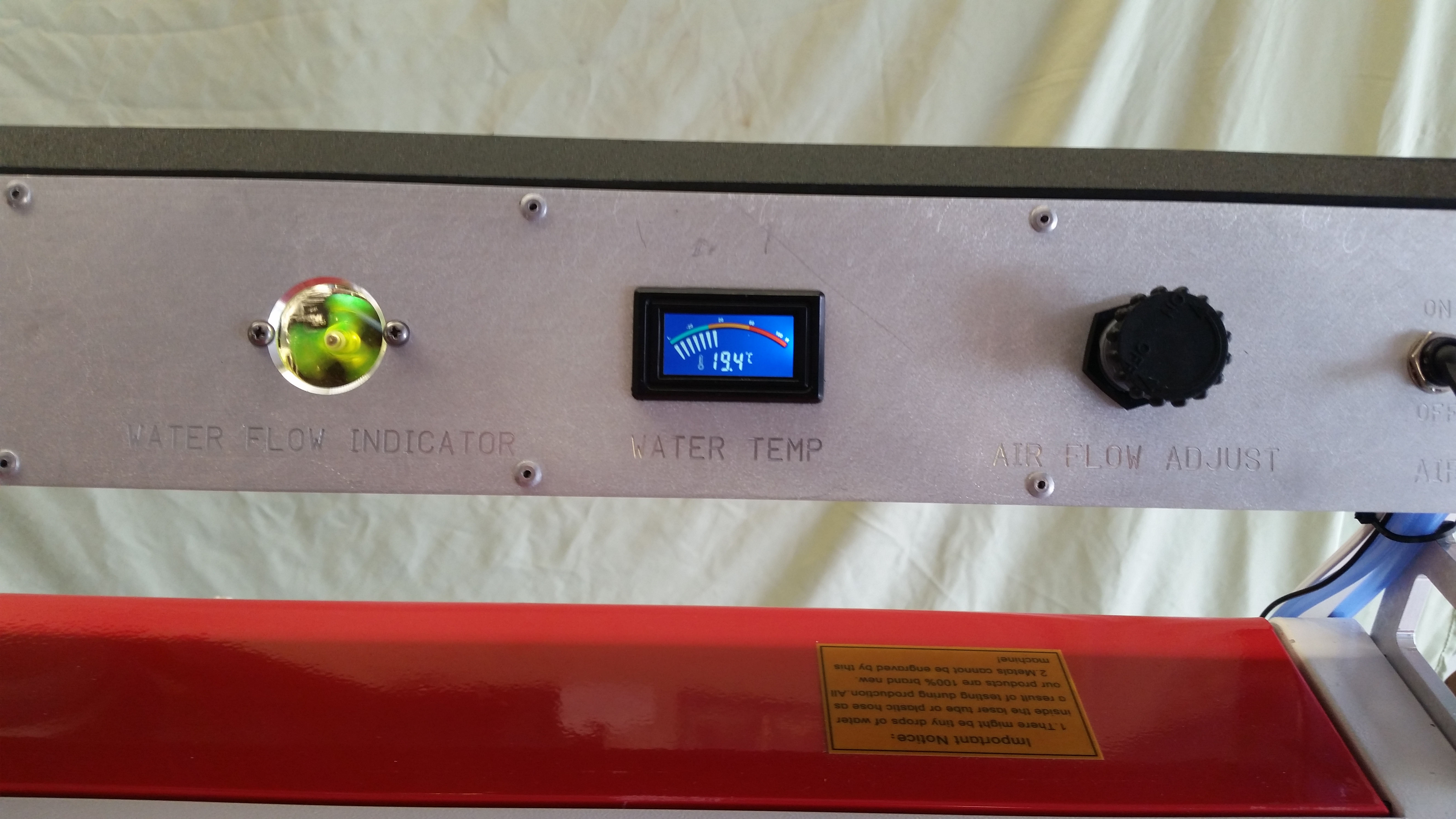
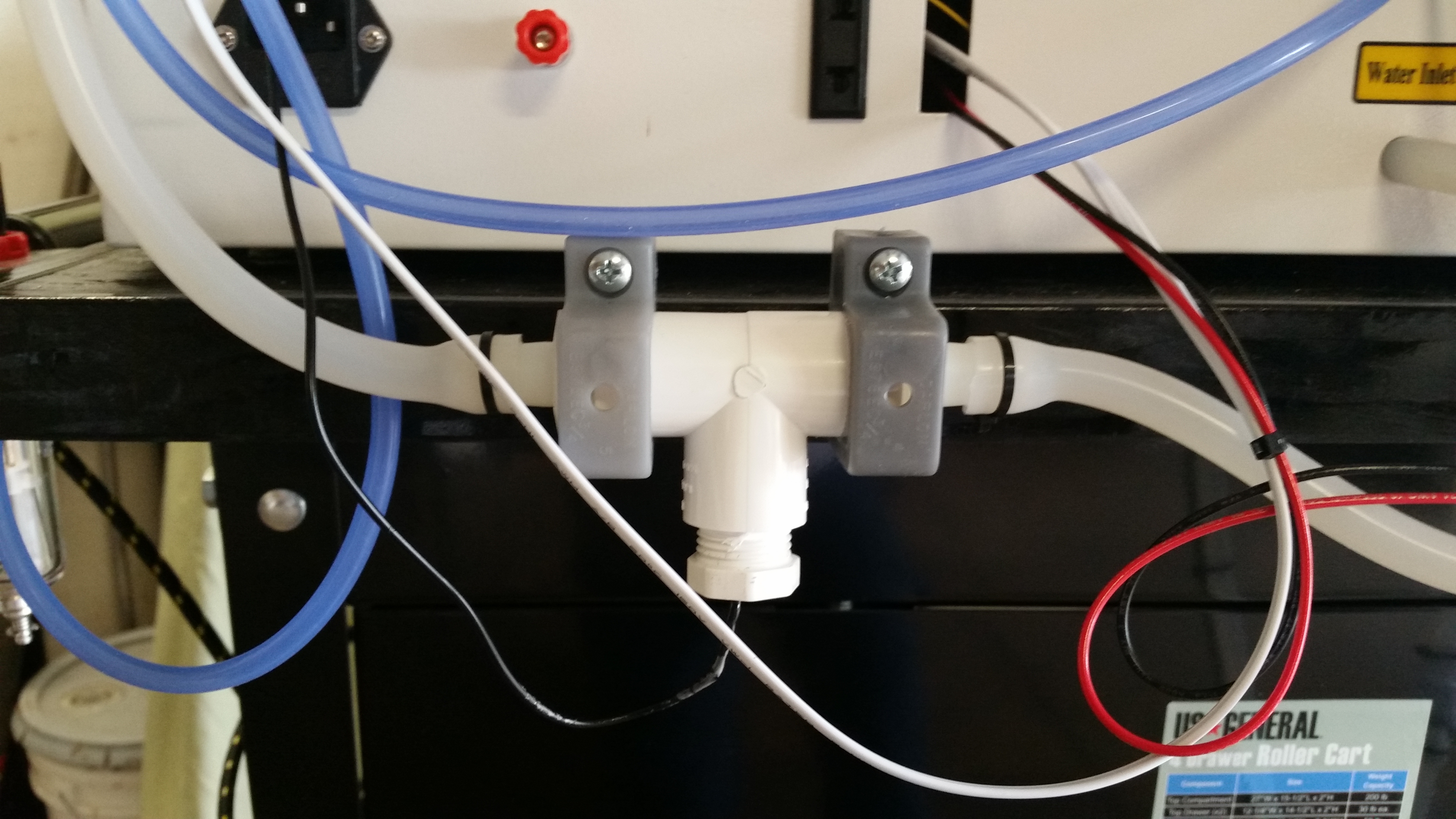
Next I replaced the coolant line with 5X8 silicon flex tubing from Lightobject for better flow, added a temp probe, pressure and a flow sensor inline.
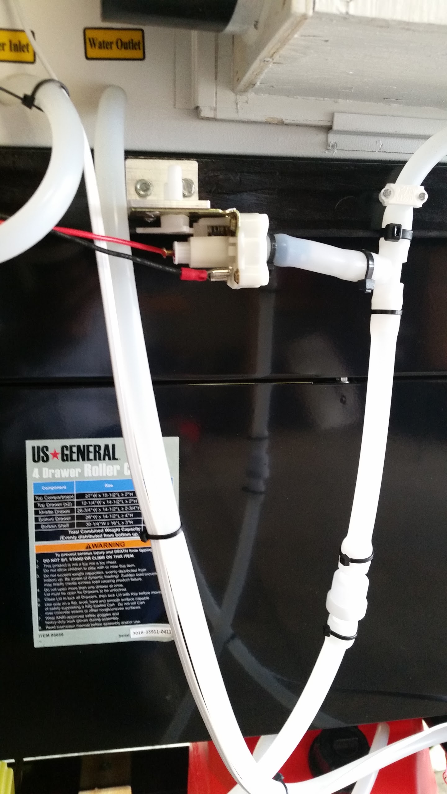
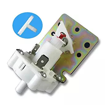
The pressure sensor LSR- H2OPRSNR (Lightobject) has a port for connecting the hose that was too small so I epoxied a larger rigid tube on it to fit the new hose added my own larger ‘T’ and tossed theirs in my parts bin. It’s wired series into the beam interrupted switch.
I mounted the temperature probe in a standard threaded ‘T’ using the epoxy to seal it.
I had earlier added a one way flow valve most likely not needed but I left it inline.
The lighted visual flow paddle wheel was off E-Bay and mounted on a control panel I had fabricated up.
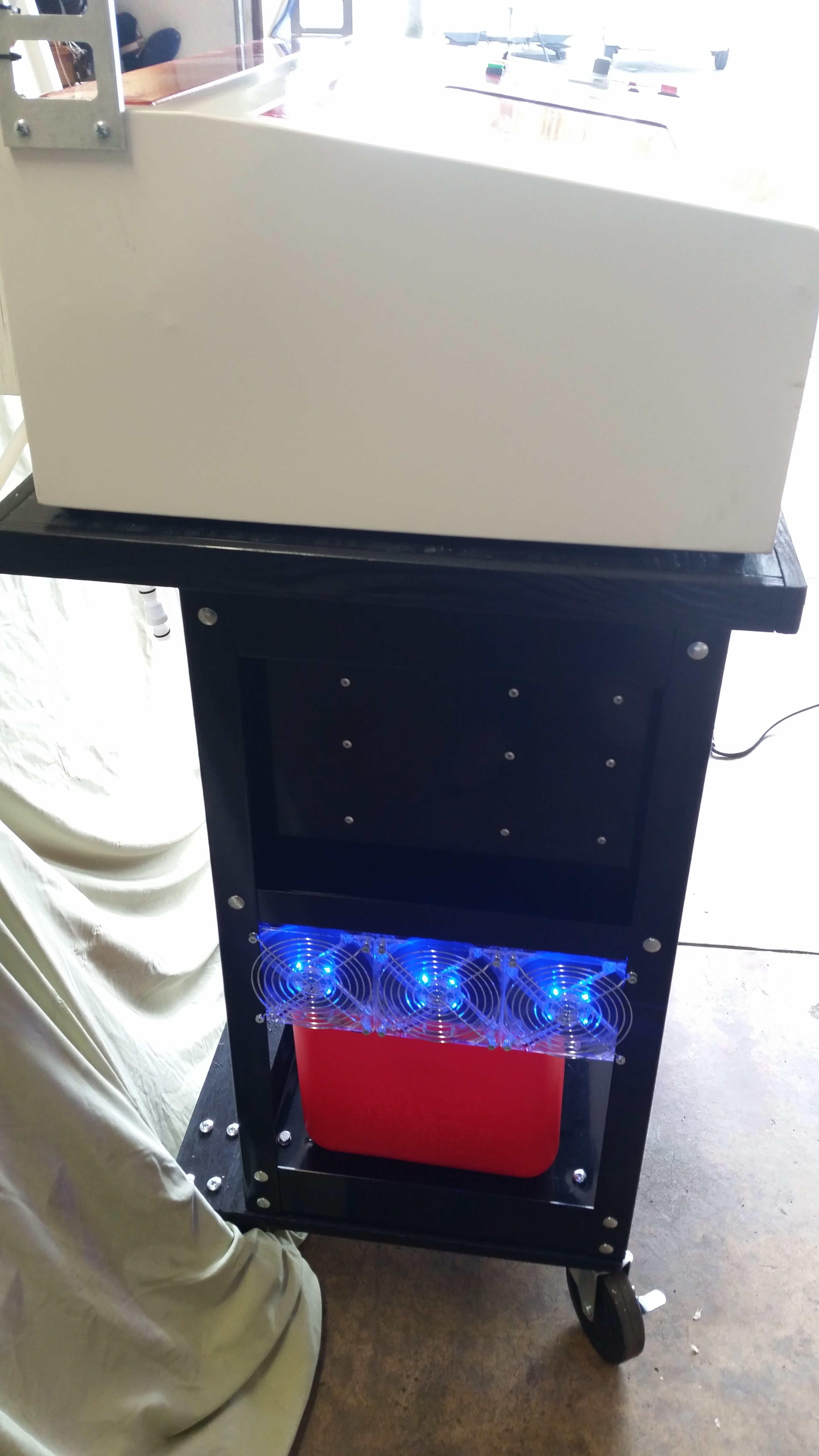
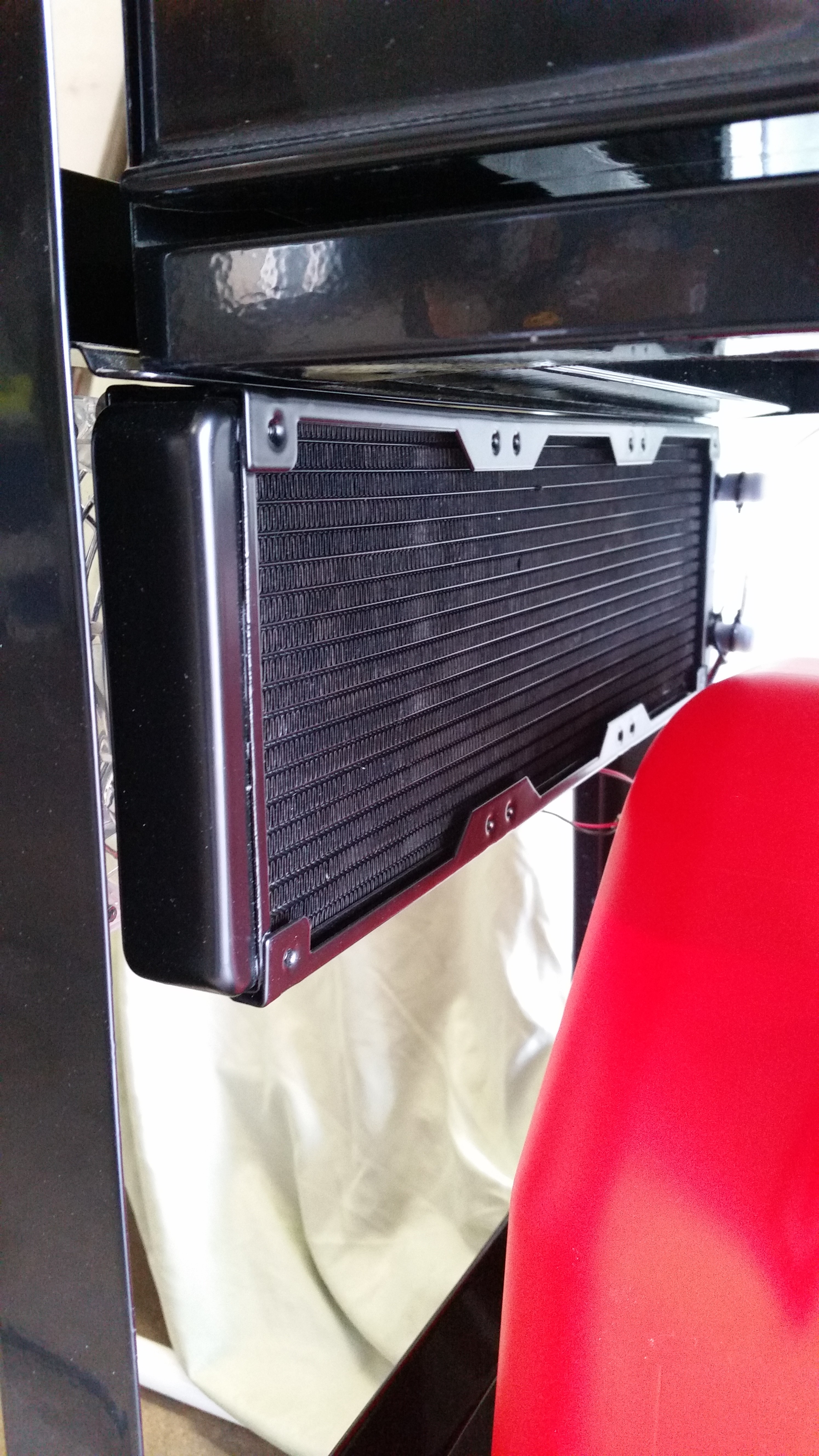
For more cooling I also added a 120 x 360mm radiator and fan system (I’m not so fond of the blue lights but the price was right).
All these 12 volt items I added are powered off a 12 volt power supply I happen to have.
This summer when it gets hot, I may consider adding a small duct to the radiator intake side from a portable AC I use in the shop for further cooling if needed.
These fan guards worked good, just got them the other day.
A little note on water pumps, you want the impeller types only as they are pretty much self regulating on pressure and too much pressure could be a bad thing. Head capacity is important, try to find one at 10 to 15 feet and 380 to 500 GPH at 1 foot otherwise you may not get good flow pushing through all the tubing. Lastly, IMO the 5 x 8 mm tubing gives you the right flow and the will fit through to holes in the back of the machine, over a half inch “T” and connector barb thus little flow restriction.
@Steve_Clark thanks. I may do something similar this summer.
On the same subject and after looking at air cooled lasers I was wondering if a vent on one end and a fan mounted on the other end of the laser compartment would help cooling. Or even port the vacuum system to that compartment? Any thoughts on that?
Have you anyway to measure the performance of this system?
I have been averaging about 20 deg C on the tube surface, which is about 1 deg C below the average water temp. You are the first person other than myself that has had any interest in tube temp, I actually started by only measuring the tube temp, but recently added the water temp
@donkjr I have two DS18B20 in TO92 cap taped to my tube, but, hrrm, my machine is still “just going to fix this quick thing”-status so don´t know how good it works
Same meters on the mirrors, to control how dirty they are - much dirt = higher temps.
I have radiator cooling too, similar to the one one @Steve_Clark is showing, in winter time it´s perfect to put the radiator outside the window, now when it´s spring i added cooler with 120w of peltiers (yes, inefficient, but does the job, 18c water temp)
I’m considering Peltiers also with a thermostat so that they only turn on when needed. I have not done the research for temperature ranges yet, or the optimum inline point. This system I have now is of course, wholly dependent on the ambient temp of the room.
I would like some reputable links on the temperature range subject if anyone has run across any.
Temp ranges can be found in some books and papers from research, where the regeneration process suffers if the temperatures start to go above 20-22c in co2 tubes. Don´t have the link here at the moment though, but linked earlier in this group.
I use a w1209 thermostat on mine, it starts to cool at 19 and turns off at 15c. With 24c ambient i get 18c with two 60w peltiers while 20min running at 12mA cutting with the laser in 23L coolant. This will differ a lot what your setting should be, depending on your ambient temps, hose lengths, flow volumes and other.
My radiator/peltier loop has a own pump and only goes back to the tank, to prevent cracking the tube with too cold water. But thats just my safety, maybe not a big issue
But keeping the tube below 20-ish is considered a fact
HP Persson, if you locate those links regarding temperature, I’d appreciate it if you would repost them. I’ll enjoy reading what you’ve found.
(Searching Google+ is a nightmare…it keeps expanding the search to all Google+ communities…not just the K40 Laser group.)
Previously, we operated our 100W machine at 20°C (as you do). But my notes from some tube vendors (now 5 years old) indicated that keeping the tube below 30°C was important (with some efficiency loss at 30°C vs 20°C).
@Kelly_Burns@donkjr Thanks guys, I don’t want to hijack the topic with my Google+ problems. The “Search Community” button appears when I run Google+ with the Chrome browser under Windows. I find similar rearranged menus on Google+ running under Android on a Nexus 7 tablet. However, there is no “Search Community” button on the tablet version (or it is well hidden). This is not the first time Google has pulled this crap.
If the water temp needs to stay 22C or below to be optimize that means cooling by refrigerant or Peltier I just did a bit of reading on the amount of wattage needed in most cases for 5 gallons of water, water flow, and normal ambient temperature ranges. Though the math is a little over my head, I’m getting 250 to 300 functional watts needed with Peltiers to cool in a reasonable time and to keep you below 20C! That seems reasonable looking at the commercial coolers out there. The ones I’ve seen start at 500 watts.
The efficiency seems to vary depending on how they are put together and the chips. But It appears that a 120 watts of Peltiers ( two 60w) are only going to yield around 40 to 45 watts of functional cooling per chip. Anyone know or got an idea of the average hourly heat/watt output of the K40 tube is during use?
I suspect with normal usage I could go with 4 or 5 60 watt Peltiers as long as is setup right.
Just thinking out loud… anyone have input or thoughts on this?
Steve, is the visual paddle wheel flow indicator visual only, or does it tie into the laser disable or interlock electronics? I see in your design you do use a pressure switch which is tied into the machine electronics. You might consider upgrading that to a true flow indicator.
If you have a kink in the water line past a pressure switch the switch would happily report pressure seen from the pump, despite the fact that no water is actually flowing in the backed up system. The flow switches I’ve seen on eBay detect actual movement of the water, and are harder to fool. One is like a spring-loaded “doggie-door” with a magnet. When water is actually flowing the door is pushed open and a magnetic reed switch is activated.
BTW, that pressure switch you referenced from LightObjects is actually a washing machine pressure switch. It’s commonly used in laser cutters. The rear side is where a shaft sticks out to select “Small”, “Medium”, or “Large” washing machine loads. (It’s probably been cut off.) When ours failed after two years, it was the rubber diaphragm that split and leaked. Apparently in the washing machine environment they are not intended to be pressurized for hours at a time as they are in a laser cutter.