So; my christmas present to myself was a whole 33Eur spent on a fly-mellow-rrf-e3 v1 stm32 based controller for ‘hyacinth’, my large format diode laser thingie.
It’s a nice and well featured board, plenty of built in features, good access to everything, open source with schematics available and it runs a well maintained port of the Duet/RRF firmware. [also; I want to test and get laserweb supporting RRF really well, but that is another story]
Setting it up on the bench was going really well, everything running, WebUI and latest firmware responding, stepper movement with some A4988 drivers. And then I swapped the A4988 drivers for a pair of MKS LV8729 drivers and all movement stopped.
After some staring at multimeters, schematics, google and even a datasheet I realised that the fly-mellow board uses pull-down transistors on it’s step, direction and enable pins to protect the STM32 from the 5v driver supply.
And the MKS LV8729 driver also has a level shifter onboard for the !ENABLE pin (which is inverted and normally high on the 8729). The end result is that the controller never pulls the enable line low enough to actually enable the stepper.
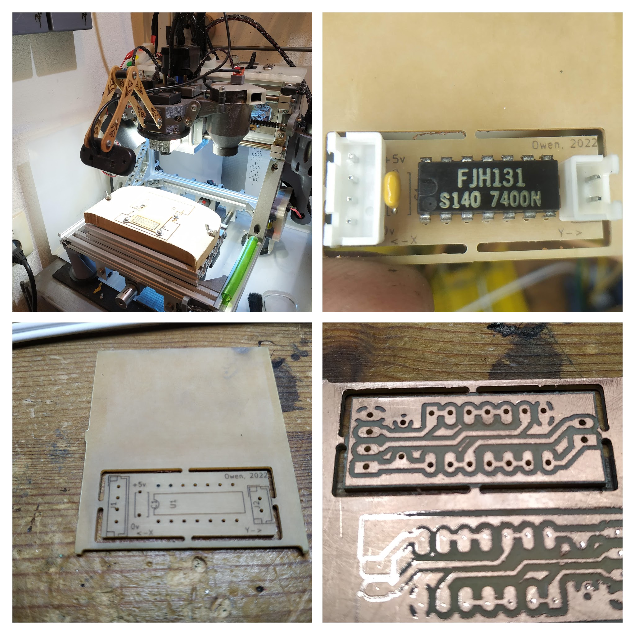
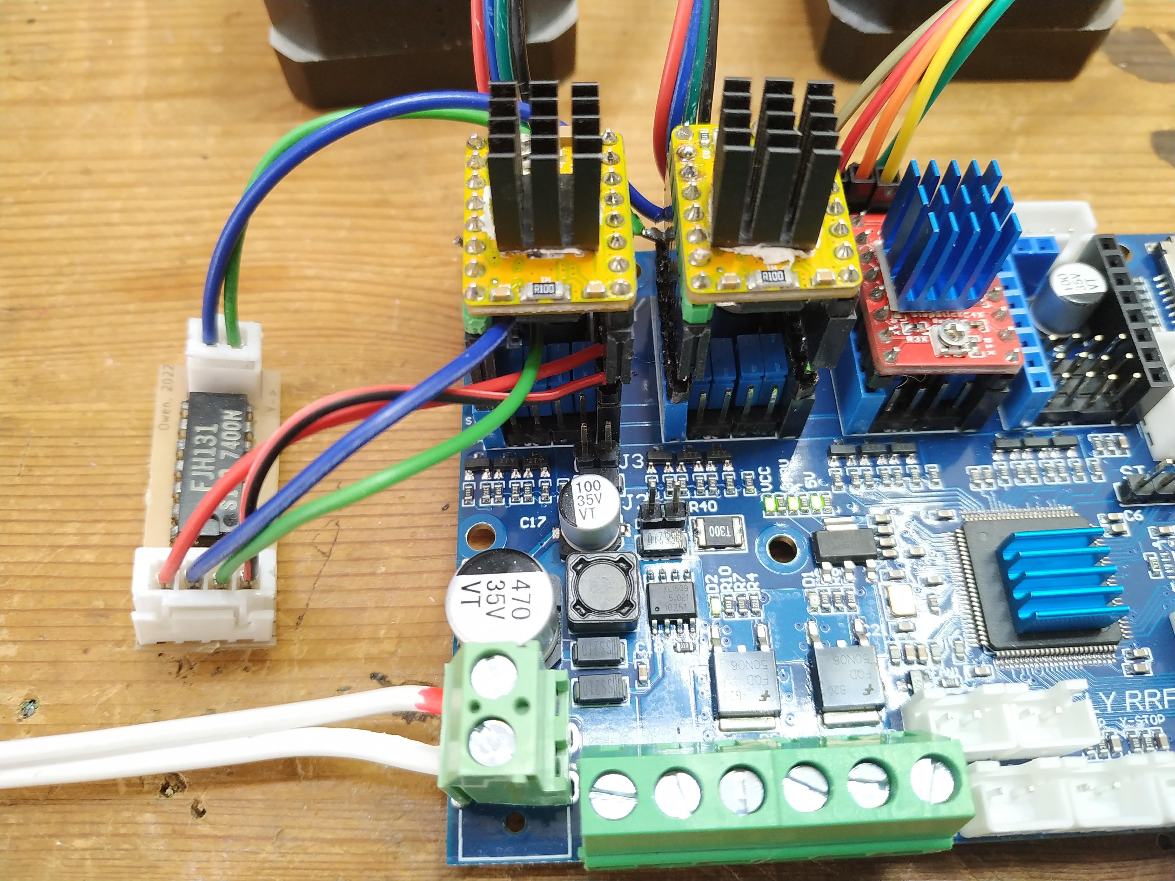
This weekend I needed some hardware to distract me from software, so I dug the board out and tested my ideas; successful result is:
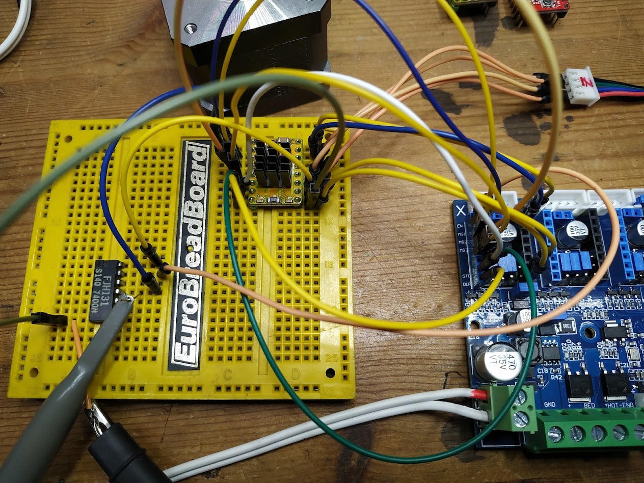
From right to left; the controller board with all it X driver pins broken out to the LV8729 on a breadboard. Except for the enable pin which goes to a 7400 quad nand gate being used with bonded inputs to make a dual non-inverting buffer, I figured that since the signals are essentially TTL voltages this would be the simplest solution.
Note that both the BreadBoard and 7400 came from my mid-80’s era stockpile of stuff mail-ordered from the back pages of ‘Hobby Electronics’, this makes me happy.
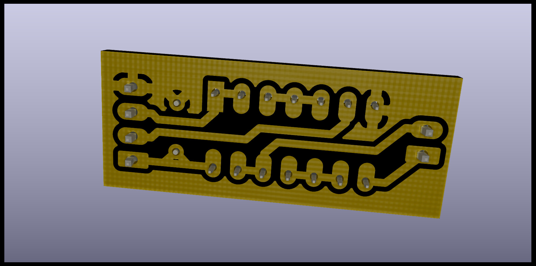
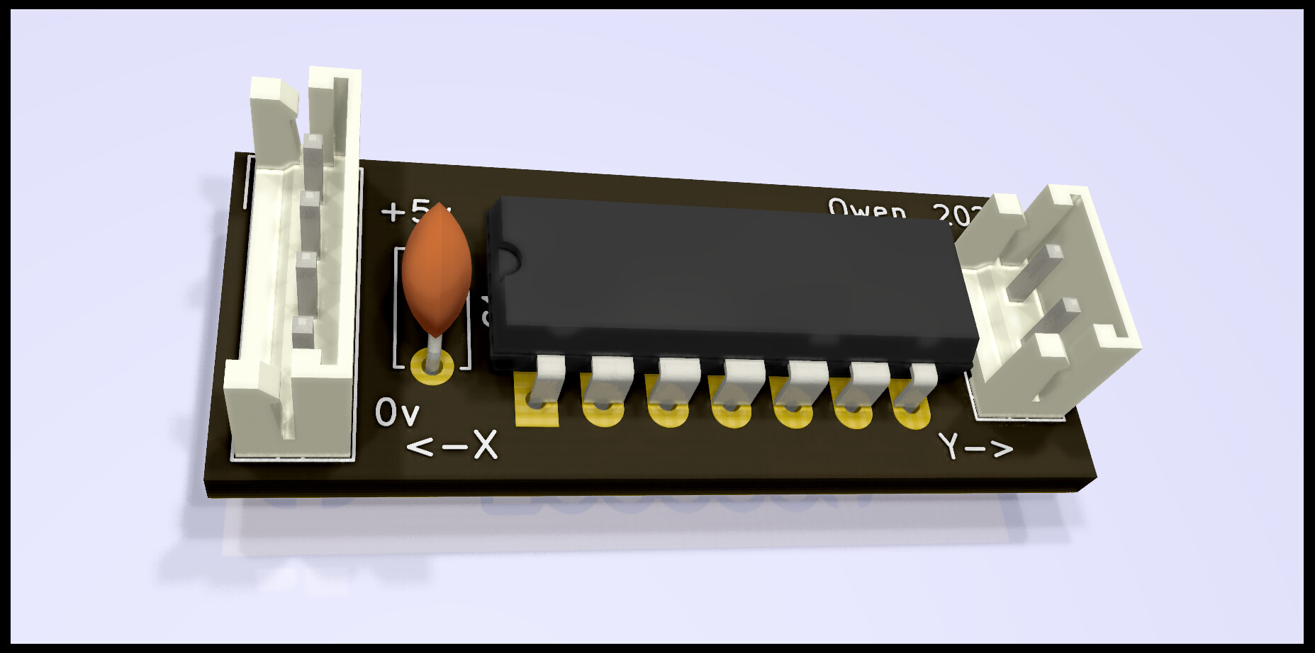
It works well, I now need to make carrier extenders that break out 5v and the enable pin, and a trivial pcb for the 7400 with nice chunky cnc-friendly tracks.

One less problem in my life