Hi, I’m a new user of K40 laser cutter. One day I had an idea and now I need to control this little wonder to get it materialized.
I use Inksacape / K40 whisperer.
I’ve been calibrating it for a few days. I think it looked pretty good. There is less than a millimeter difference in the focal point of the four corners of the machine. The cut is quite good except when describing a curve up and to the right. When I cut a circle, between ten and eleven the cut presents small tremors.
Reading in the forum it occurred to me to tighten the x-axis belt but nothing more. Anyone know if I can try any other solution?
Thanks a lot.
Good morning everyone and especially Nedman, thanks.
Before I forget it:
Before making this consultation I had also leveled the machine and its bed, polished the small imperfections in the lacquer of the x-axis and lubricated the y-axis.
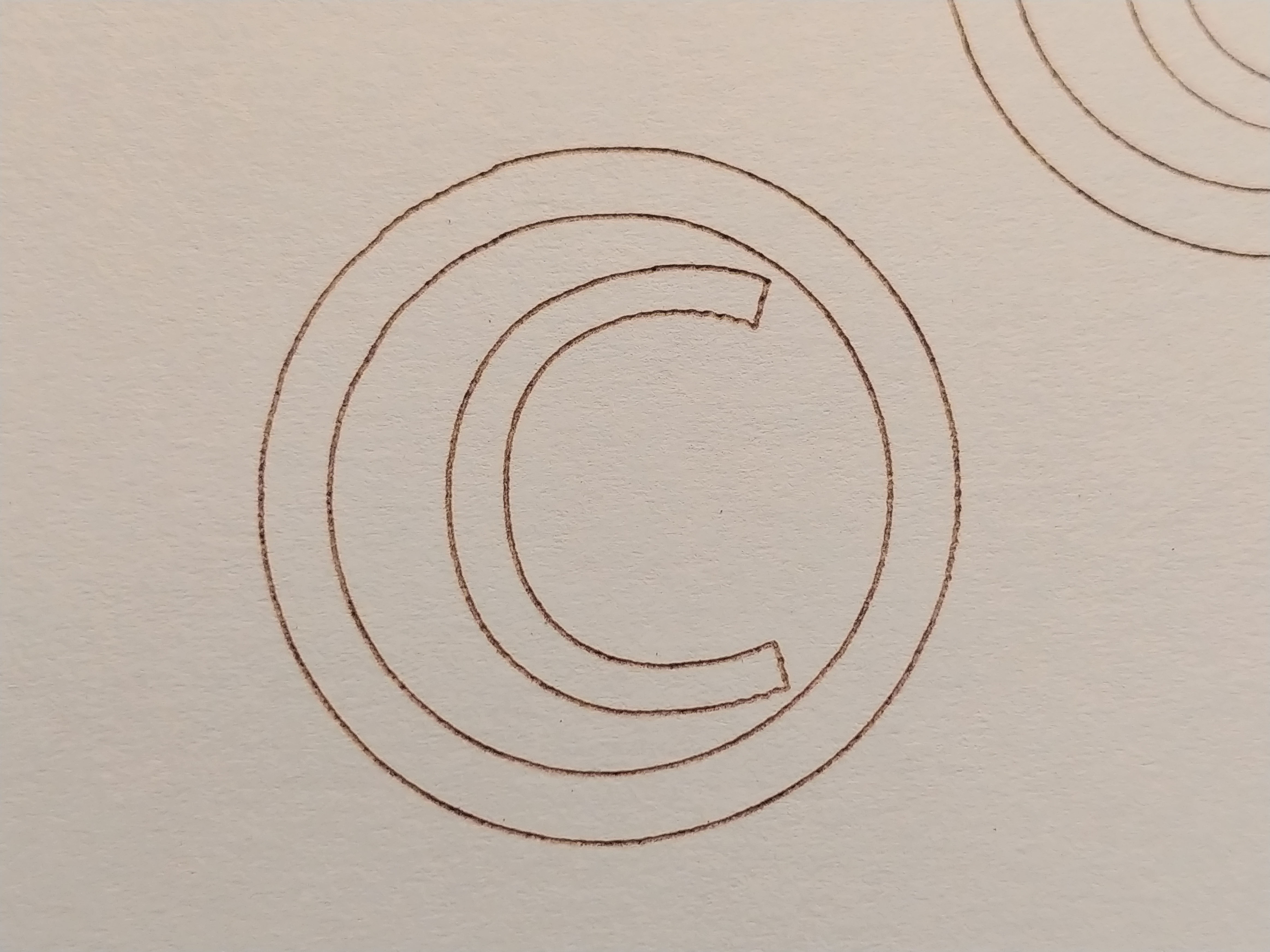
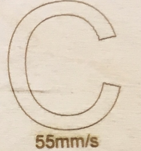
Here I leave a print test on 80gr paper at a speed of 30 mms. In it you can see that the outside of the letter c is incorrect but inside it is fine. The difference is the cutting direction, I think.
Some things on the machine that I don’t know if they are correct although they seem like design decisions. One is the y-axis, it is not perfectly parallel to the chassis. In its right part it is four millimeters closer to the chassis than in the left part. On the other hand I worry about the white wheels of the x-axis. When I move the two wheels on the right the nozzle moves but if I move the two wheels on the right the nozzle does not move. Are these features correct on my machine?
You can insert an image with the button in the editor window.
For a large image, insert it on its own line.
If you make a video as @NedMan requested, the best thing is to upload it to youtube and then include a link to youtube, and just put the youtube link on its own line in the editor; that will make the video show up inline and make it easy to view.
So when doing a vector engrave I have always limited my speed to 25mm/s because I would see artifacts like this. Never need to vector egrave faster then that so I’ve never spent any time investigating this phenomenon.
So I’ve decided to do a little investigation.
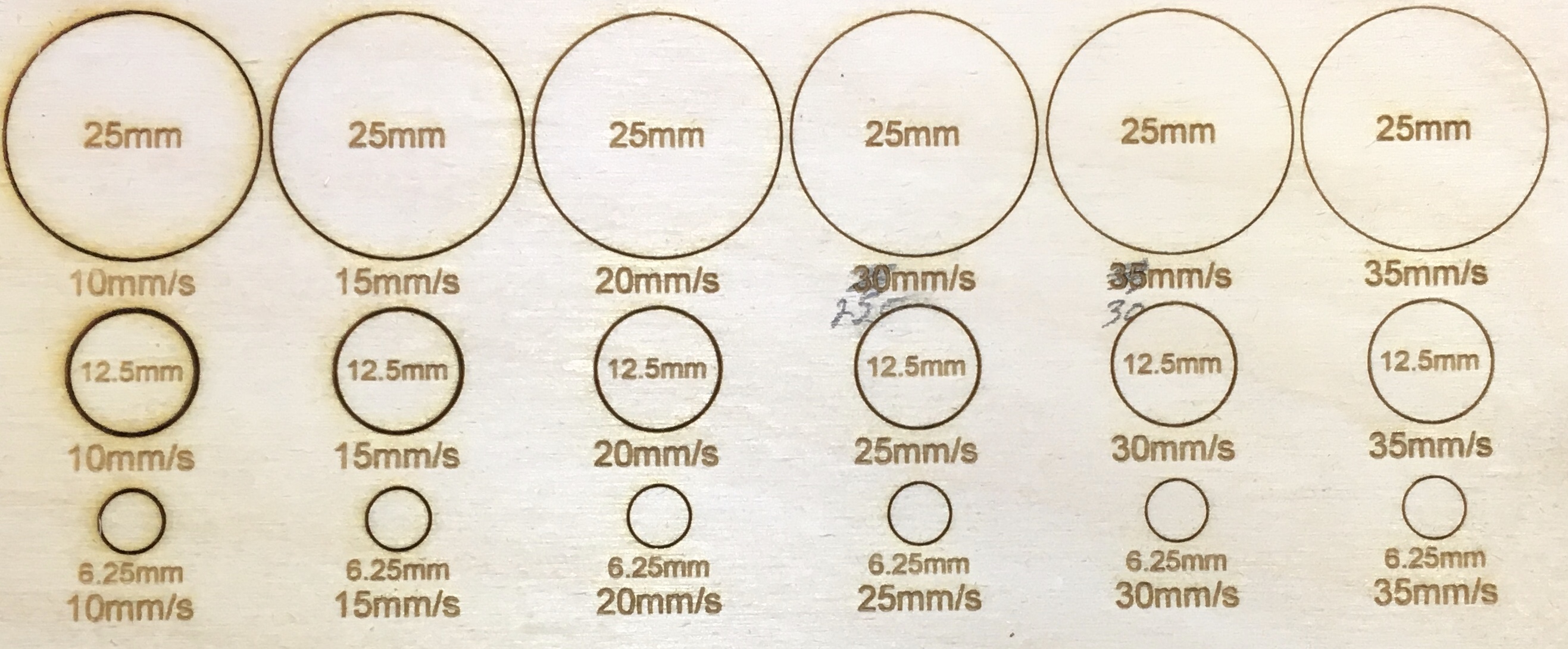
Did a series of circle vector engraves at different speeds and circle diameters.
Surprisingly I didn’t seen any artifacting up to 35mm/s at any curve radius. If you really magnify the 25mm circles at higher speed you can see a tiny amount. Seems to imply if there is a constant smooth acceleration of the laser head the artifact effect doesn’t really occur. Stock controller.
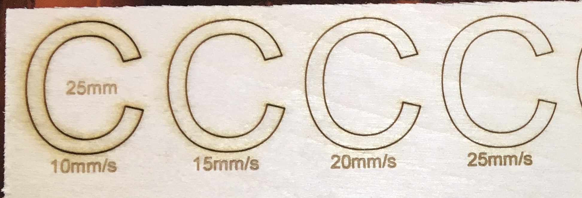
Next tried letter Cs, which are about 25mm in size, at different speeds.
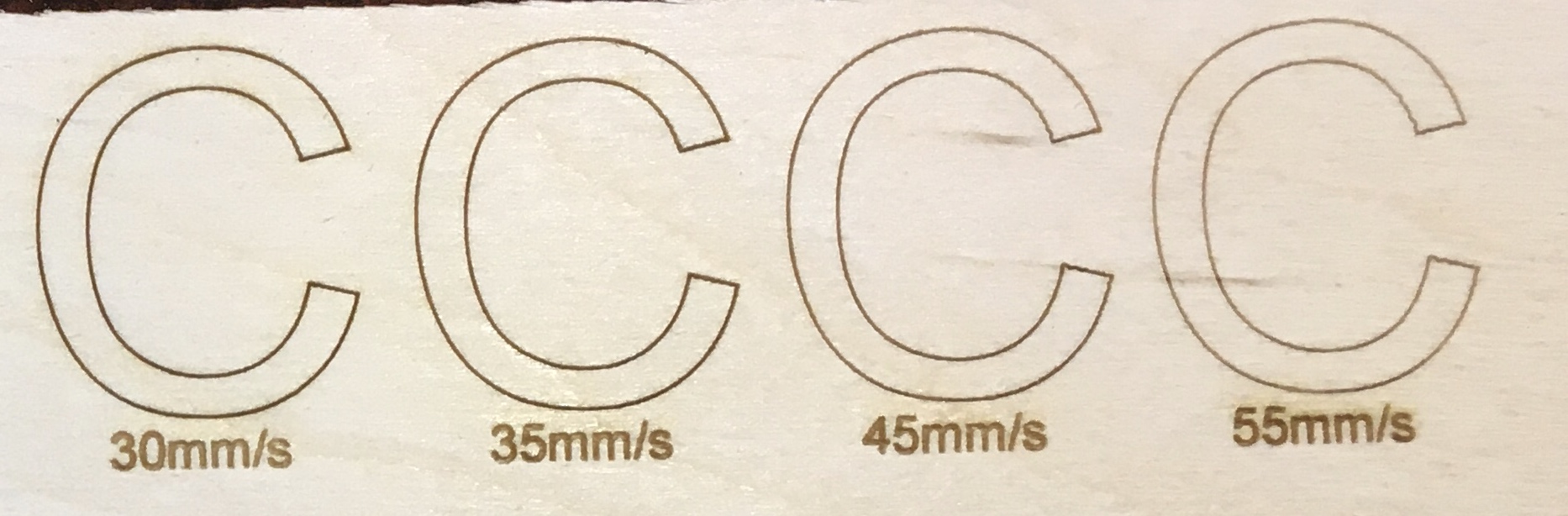
So we now start to see the artifacting becoming more pronounced at speeds at 30mm/s and above,
The path of the engrave starts at the top and moves initially clockwise. The effect is most pronounced around the ends of the C. I suspect this is related to how the controller is handling the acceleration and deceleration of the head through the stepper motors. @cprezzi@Scorch@raykholo@pauldg123@donkjr anyone want to throw their thoughts in?
The wiggles you see are a function of the acceleration, stiffness of the gantry and the mass of the moving components. In any CNC system there are trade-offs to be made. If the acceleration is decreased the wiggles will go away but the engraving speed will vary greatly around the corners resulting in the corners being engraved at significantly a slower speed.
Additionally adding air assist and/or LED lasers to the laser head changes the mass and in turn affects the wiggles. Changing the tension on the belts changes the stiffness of the belt and also affects the wiggles.
My machine seems to vibrate more at around 25 mm/s but then as I increases speed from there I get less vibration until I get higher in the 30’s. I am guessing my machine has a resonant frequency (a frequency that the system will naturally vibrate at.) that gets excited when I am engraving at 25 mm/s.
Indeed it seems to be acceleration and deceleration artifacts. Instead of a C can you repeat the test with horizontal and vertical lines ( maybe also 45 degree lines), so we can confirm or reject this hypothesis?
Another hypothesis that I have is that the wood burns at different rates. If the grain alternates between hard/soft fibers then we could see the peaks and valleys … I think this is not the case but you could potentially see that in the line test too. Okay let’s us know what you find since I am intrigued!
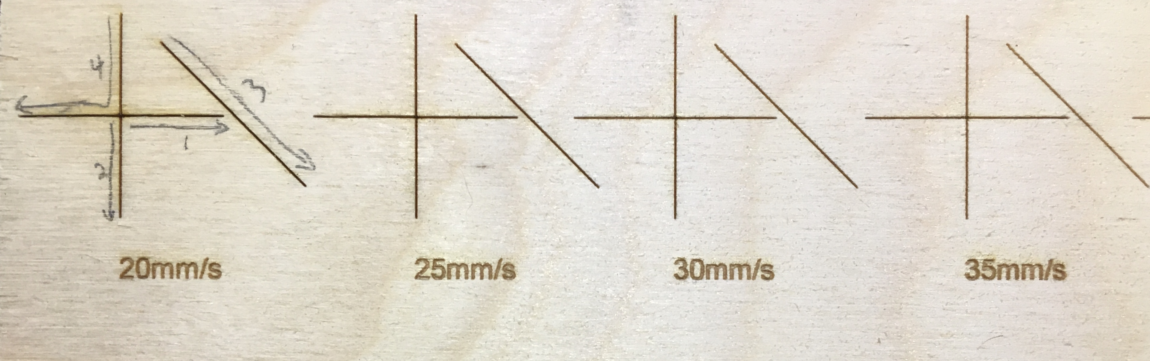
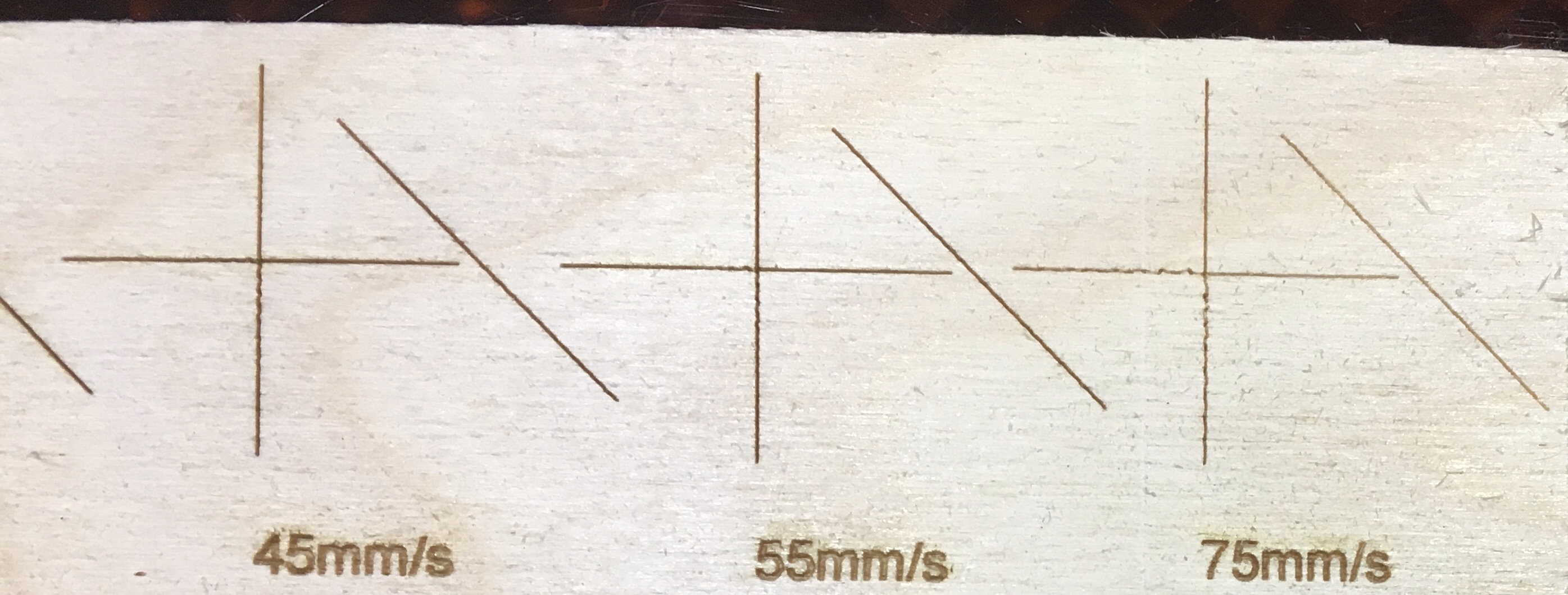
So I made a horizontal and a vertical line as a cross to save some space and then did a 45deg line on the side. I grouped them together thinking they would just engrave each line separately. Instead it parsed it strangely which gave some interesting results.
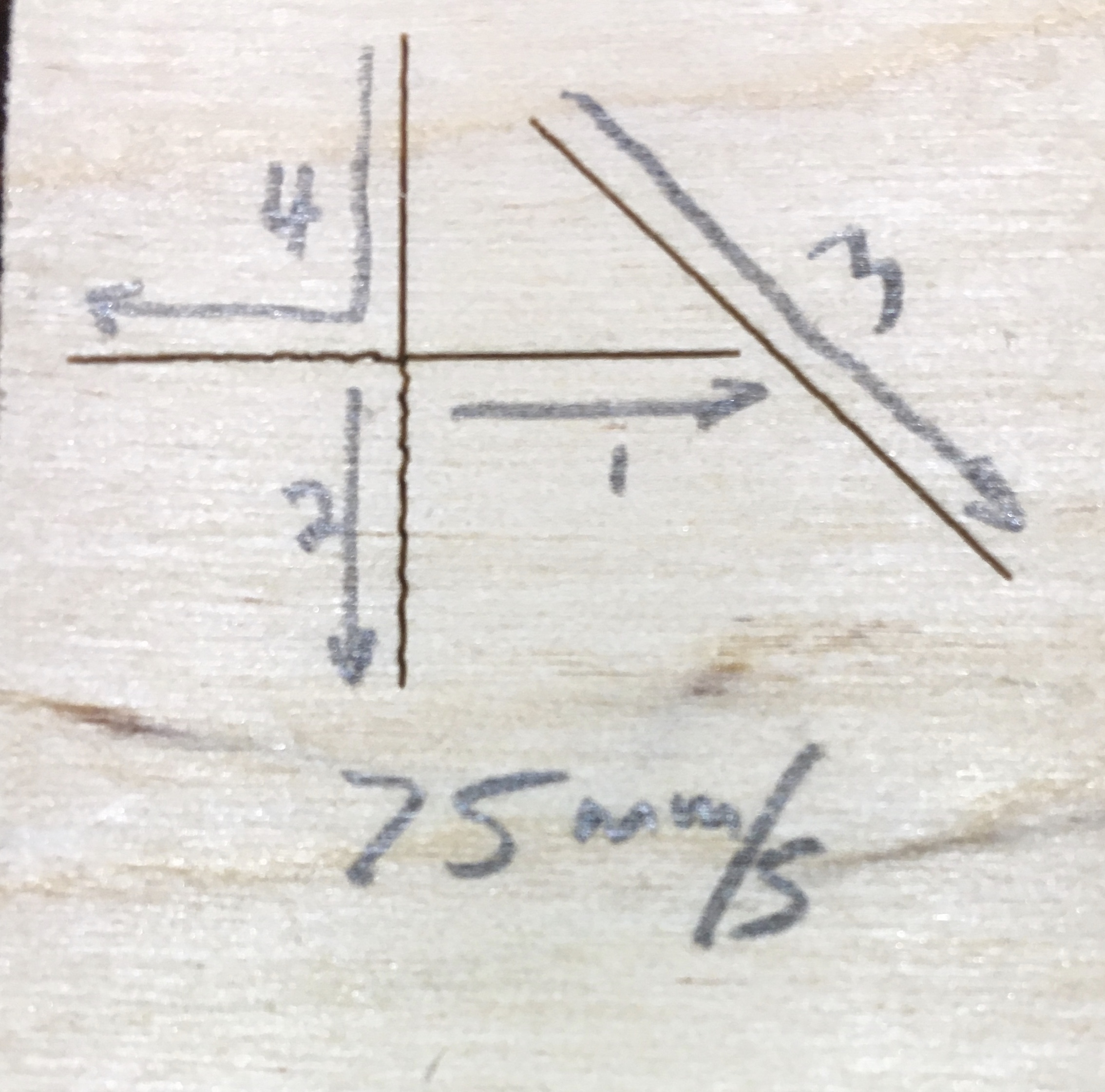
It started in the middle of the cross and did the right leg, then moved back to the center and did the bottom leg. Moved back to the top, retracting farther back, and did the 45deg. Then moved diagonally back up the line, retracted farther back, and did the top and left leg on the cross in one continuous movement.
So if it starts from a momentary pause, or delay, it seems to be fine. We see the wiggles if it does not have a delay / pause between direction changes. Also the bottom leg has a longer vibration wiggle then the left leg. Seems to suggest that the vibration of the head is more pronounced along the x-axis direction?
It’s not realy accelleration artifacts, but direction change overswing. Every time the direction is changed by 90 degree, there is overswing that gets less and less over time (distance). If you would wait a second before changing the direction (which is hard for circles) it would probably go away.
The strength of the overswing is depending on the accelleration and stiffness of the system. Decreasing the accelleration should decrease this effect, but on firmware that does not compensate laser power to the accelleration / decelleration, you would get darker zones during acc/dec.
By the way: This effect is widely known for 3d printers, where the overswing is visible after carners.
Tightening the belts and reails could reduce this effect to a certain level.
Some firmwares (like marlin and repetier) have a jerk setting for that, which does a small rounding of corners to reduce the overswing.
I’m sorry, I’m so sorry for taking so long. Yesterday afternoon I found the bug and I started directly to cut my design and improve it. I’m a little stressed, hehe.
Thank you so much everyone. I will try to update the post to be as useful as possible for others.
The problem was mechanical. More specifically on the two left wheels of the x-axis. I had to adjust the wheels using the upper screw. The thread of these screws is very poor. I do not rule out that it can give more problems in the future. So in order for the machine to work properly when any of the wheels is turned manually the device has to move.
Again, a million thanks to everyone for helping me.
No worries, glad you got it figured out. It was a good exercise to get more of an insight into the problem.
Thank you for reporting back your fix, makes it useful for others as you noted.
For your future reference, the carriage wheels are on eccentric posts. Meaning that the wheels are not attached to the center of the posts. So if you loosen the screw at the bottom of the post you can rotate the post to move the wheel closer to the rail.