First off, thank you to all the developers. Great software and great community.
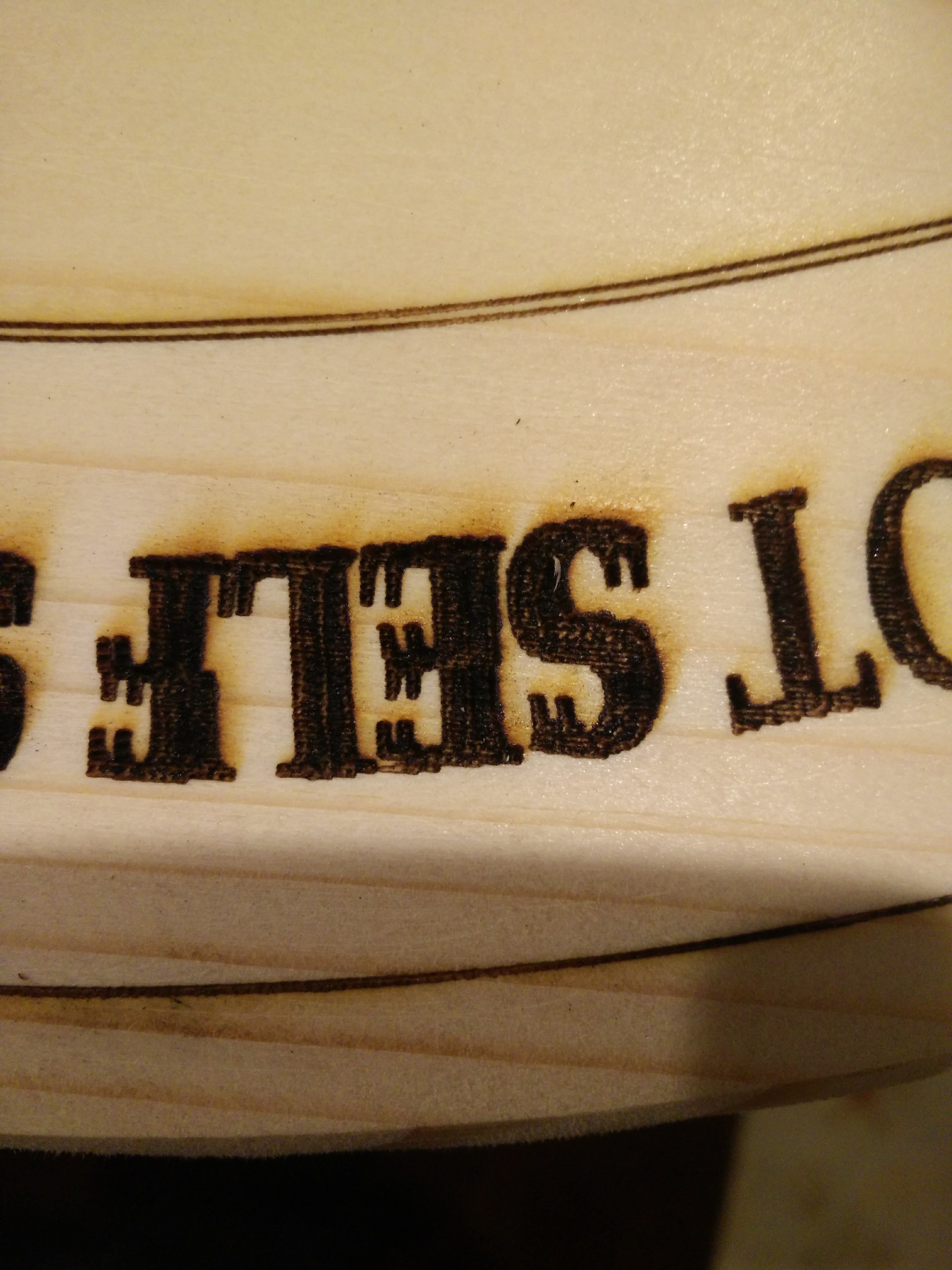
An issue I’ve been running into during my laser operations is that when I conduct a laser fill path the fill can be pixelated, especially when using a very fine curving text. The horizontal movement tends to cause that issue from my observation. To fix that I’ve tried dozens of times to follow up a laser fill path with a laser cut to try and solidify the outline of text. More often than not the text ends up misaligning since, in many cases I’m conducting extensive laser fill paths (500,000+ lines of gcode). This can be seen in one of the attached pictures (“SELF”).
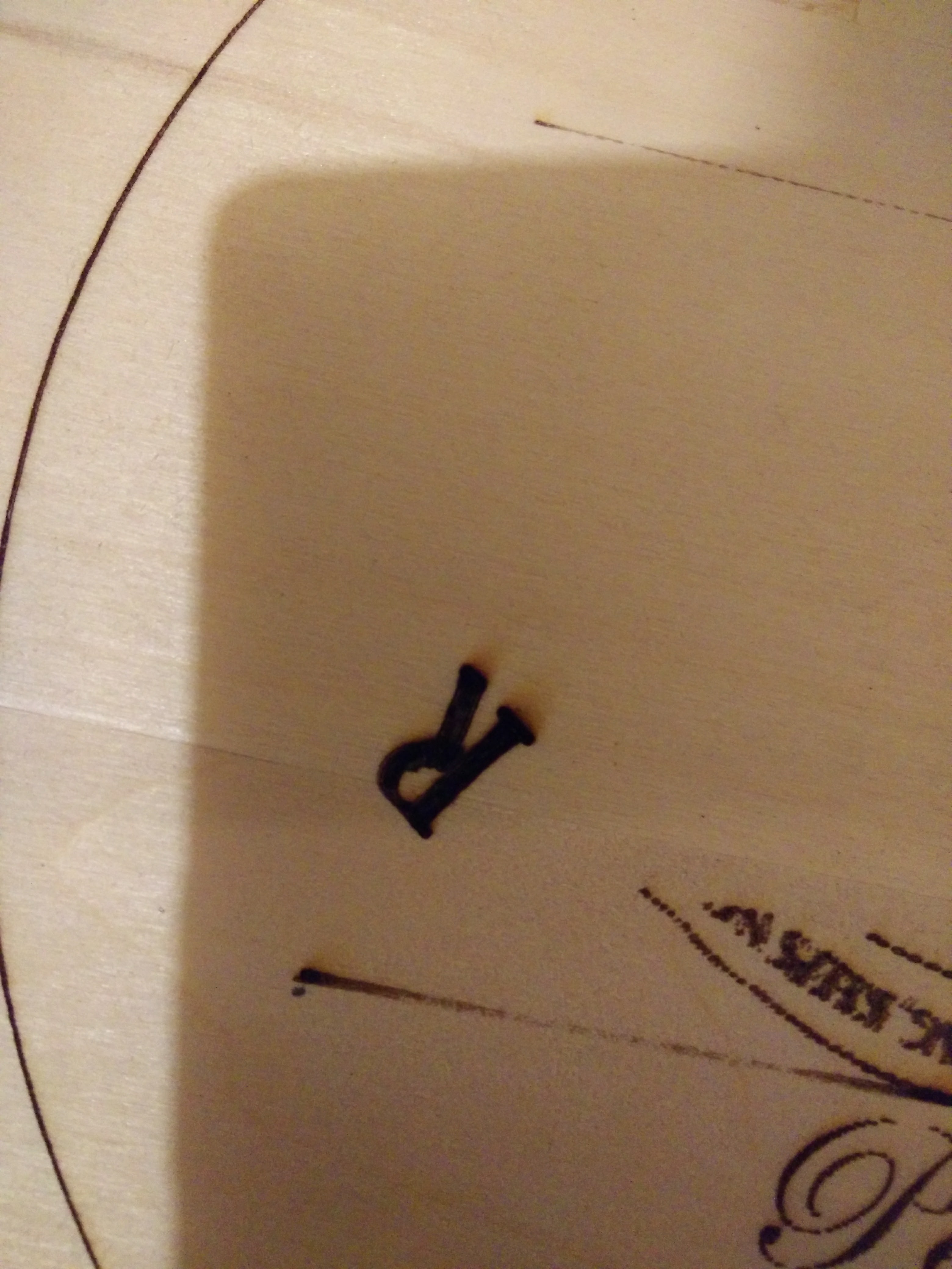
However, today I was playing with using a mill pocket action to burn a fill path and it worked amazingly, as the laser path followed a similar pocket cut working from the outside in along the pattern of the object…thus very clean lines and very efficient laser movement without 2 operations (other picture of the letter “R”). The problem is that I end up having to trick the software into thinking I’m conducting a mill operation with z movements and offsets from 0mm rather than my standard z height of 15mm for laser operations.
Would it be possible to add an action that allows for laser operations that generate similar CAM mill pocket paths with no z movement and a starting z height, aka “Laser Pocket Fill”? I’d like to donate to this problem.