FastLED never drives red at full brightness?
Recently experimenting with a single pixel (I used ws2811 IC with three 5050 rgb LED as depicted in ws2811 datasheet) I just ran this code “leds[0]=CRGB::White;” I measured the voltage of output pins of the IC, I read 4.49V for red output, I did the same with Adafruit NeoPixel library and I read 2.7V for red! So the red color using Adafruit NeoPixel is brighter. (differences for green and blue were negligible). Is it done intentionally? I did the measurements with my multimeter set on for DC voltage.
Hi @Ahmad_Sajadian the IC outputs a PWM waveform. Use an oscilloscope to see the waveform.
You can not measure reliably or accurately with a regular DMM.
Also remember that the power requirements for red LED is different to Blue or Green LED.
Also,
What did you set the brightness level to?
What did you set power management to?
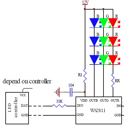
My interpretation of this post was he was measuring the voltage drop in ‘RR’ noted on the schematic, not sure where else you’d measure that large of a discrepancy in this particular system.
And while yes, the IC uses PWM for dimming, it uses constant current regulation for physically powering the LEDs which means hypothetically, the LEDs are supplied with as much voltage (up to VCC) required for the specified current (18mA +/- 2mA if I remember correctly ).
You’re going to need to test the red, and only the red, to get a little bit more in depth here.
Set an LED to CRGB(255,0,0) and measure the current to the LED with both libraries, 20ma vs 20ma on the same die is as equal as you can get.
Else, use an oscilloscope to see the specific waveform lol.
You aren’t by chance using color correction are you?
Thanks for your comments. @Stuart_Taylor your right It is PWM but I have no oscilloscope so I just measured the DC voltage to get some Idea, and the brightness difference could easily be seen.
@Jarrod_Wagner I had pasted the setup function from the demoreel100 example and at the end of LED definition command I hadn’t payed attention to the color correction setCorrection(TypicalLEDStrip) ! I deleted it and it’s ok!
Do you know the PWM frequency of ws2811? The chip changes the brightness by altering the duty cycle, right? does duty cycle change between exactly 0% and 100%? I think it’s not 0% exactly, if it were so I should read 0V with a DMM, while I read 0.3-0.4V.
Hi @Jarrod_Wagner true, but he said he measured across the output pins of the IC, not across the led.
There will be differences between the libraries. But the DC range on a DMM will likley add more uncertainty rather than prove anything.
That said, i’ve added it to my to-do list (once i’m let out of the kitchen).
Merry festivus!
@Ahmad_Sajadian I’ve tried to find both the PWM frequency and synchronicity for each channel to no avail. Don’t have a scope either so it’s just going to have to wait for a) me to get one b) someone else to measure 
And I think most chips are 5-95% duty cycle, anything lower/higher than that is challenging to hit, but I’m not sure about the WS series chips.
Also, were you using 5v or 12v as the supply for the series LEDs?
Right now - the only thing that FastLED does differently from the adafruit library (and is a side effect of the inline scaling, which will be fixed soon, i’m just putting off the ugly asm work it is going to take in order to fix it) is that 255’s get sent out as 254. Also - make sure that you aren’t setting anything for color correction/temperature or brightness - as that will also add more scaling to things.
AH! Did you by any chance go into Sketch | “Include Library” and select FastLED? That seems to insist on including all the header files in a way that it really shouldn’t be doing.
@Jarrod_Wagner I don’t have access to a scope, I wish someone who has make some measurements and let us know!
In FastLED documentation Chipset reference It says PWM freq of ws2811/2812 is 400Hz, I don’t know if it’s from another source or it has been directly measured.
The voltages I reported was by using a 12V source. By using 5V supply and a 4.7k resistor between output and VCC to measure the lowest voltage, I read about 03-.0.4V. (The output is a constant current source so I added the resistor so that I can find out the lowest voltage of the output) so at best I think as you say the duty cycle is 5% at full brightness.
@Daniel_Garcia I always open one of the examples and delete unwanted parts, so I never do that!