I have an EleksMaker ManaSE v3.1 plotter on which I would like to mount a laser that needs two command signals: a digital signal (0-5V) for enabling (on / off) and an analog signal (0-5V) to adjust the power. By applying a low pass filter to the output of pin 11 (PWM) I should get the analog signal I need. But where could I get the digital on / off signal instead? Generally on CNCs based on GRBL firmware it is pin 12 that gives the enable signal, but on this board it does not seem to be connected. Do you have any suggestions by chance?
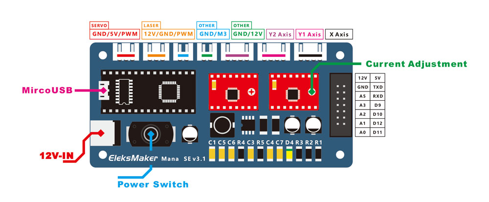
In the attached image you can see that there is a connector called M3, which in the Gcode indicates the enabling of the tool, but I don’t know if it can have that meaning on this board
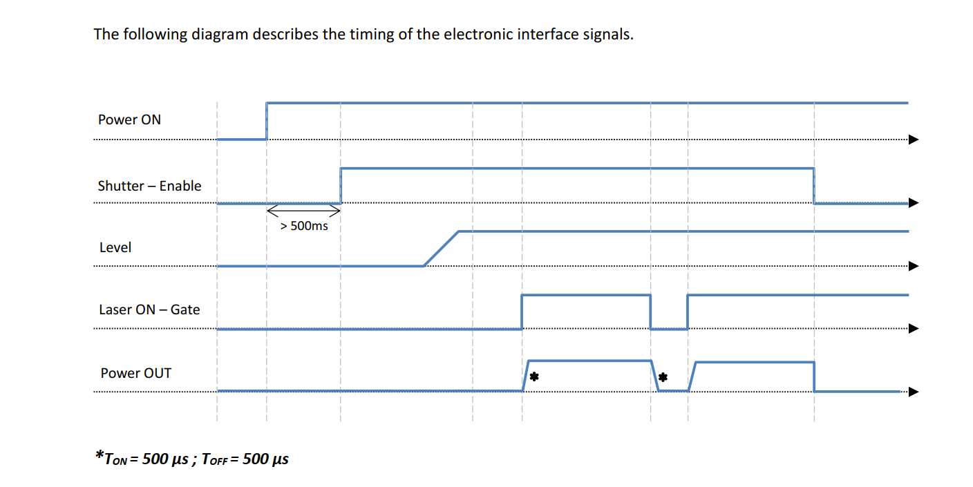
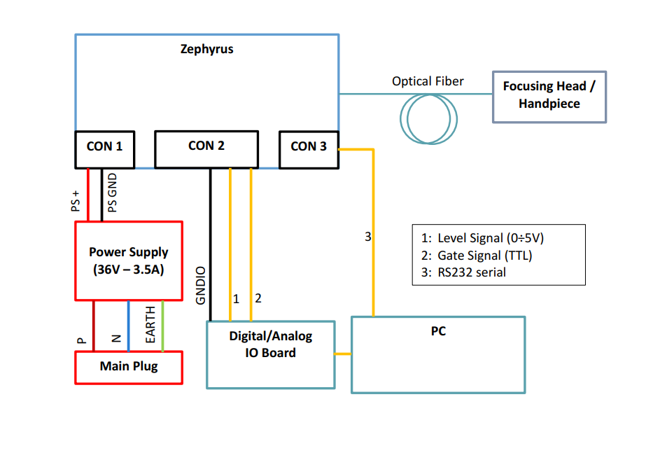
It is a 30W blue light laser from Lyocon named ZEPHYRUS.
The forum does not allow me to attach the manual of the laser system, so I insert a screenshot of the signals
The M3 output looks interesting but without the schematics I cannot tell how it is implemented?
Of course you could run a test program and see how the M3 behaves?
I suppose you could derive a on/off signal from the PWM signal but that feels pretty klugy and complicated, and I am not sure it would achieve the required timing. ?
Unfortunately there is no information about the M3 port on the laser plotter wiki page, and the official forum is down.
How could I empirically understand what kind of signal is associated with it? If I don’t know the function it performs I wouldn’t even know what g-code to write to test the port
I believe that I could read the PWM signal using an Arduino board, and associate an analog signal produced by an I2C DAC or a low pass filter to the read value.
Then, when the Arduino board detects a PWM signal different than zero percent duty cycle, simultaneously with the generation of the corresponding analog signal, it sends a 5V TTL signal to the laser gate for enable it. On the other hand, when the duty cylce goes to zero, the Arduino sends the 0V signal to the gate.
What do you think? It might work?
I was thinking that the M3 output may be correlated with an M3 Gcode command “start spindle”. If that is true you should be able to connect up the board and issue it a M3 command and see if the M3 output changes.
The devil is in the detail. Delays between the Arduino’s detection of an on or off condition from measuring the PWM duty cycle and what the controller thinks the machine is doing during that time is bound to create a race problem.
Example: the controller asserts PWM and starts movement, sometime later the Arduino independently detects PWM is ON and then enables and starts PWM but the mechanism has already moved.
You may also be able to do this in logic so that it is faster.
It would be useful to know why both a TTL enable and PWM is necessary.
Noodling the problem:
What if the enable was static. i.e. the enable is a switch that allows the PWM at the start of a job and turned off at the end. Or does the TTL enable need to drop any time the PWM is not asserted.
I will take a closer look at the manual you linked.
The gcode command M3 means spindle on clockwise, so I guess the M3 port is connected to D13. If so, you could use that port to enable your laser. Just try with a voltmeter if an M3 command delivers 5V on the M3 port, and M5 stops the signal.
Yes, I understand the problem. Thanks for the very interesting observation
Not being an electronics expert I’m not sure I understand this tip correctly. Could you expand the concept further?
Effectively, I could give the enable signal at the start of the cycle and the shutdown signal at the end of the cycle.
As long as the analog power signal is 0, the laser remains “Off”, while it would switch “on” whenever it receives a non-zero analog signal.
In this case I should remember from G-code to give a pwm signal equal to zero when the laser is in a “transit” area, so as not to engrave unwanted parts. So instead of giving G-code M3 and M5 for the on / off signals, use the S command with a value equal to 0 for switching “off” and non-zero for switching “on”. Correct?
Thanks for the reply
Currently the firmware I am using is GRBL 0.9
Does the advice you have given me remain valid or do you suggest me to update the firmware?
Anyway I will try to follow the advice and test the M3 port
Thanks for the reply
So the M3 port should actually carry the laser power on signal, right? Even if my firmware is 0.9?
Also I currently use a GUI called Laser GRBL which does not allow me to change the $ 32 parameter. I attach the link of the configurable parameters.
However I should be able to write the parameter $ 32 = 1 by sending it along with the G-code, right? Otherwise I think I should switch to another GUI like Universal Gcode Sender
From above the suggestion is that you can use the M3 output as the laser-on signal but you need to test it first using the M3 gcode command.
Try it with the current firmware first…
I did the test you suggested and effectively by running the g-code M3, on the M3 port, I read a voltage of 12 V. Instead with the g-code M5 I read a voltage of 0V.
Honestly I expected a 5V signal, being the ManaSE board based on Arduino Nano, but I could still take advantage of this signal by inserting a module that transforms 12V into 5V.
An oddity that I found however is that by testing the GNDs of the other ports I never get 0V but about 1.3V
Can you more detail on how and with what you are making these measurements.
Are you saying that when you assert an M3 it goes to 12V and then asserting an M5 is goes to 0v?
I am guessing that the GND/M3 output is actually motor control and you would expect that to be 0-12V.
Note that there are two versions of the Mana board and the difference are
---- ConnectorTable ----
Ref#
Old Label
New Label
comment
1
Servo
Servo
xx
2
Laser
Laser
xx
3
n/a
Other (M3)
this is new with m3 control
4
Motor
Other (12v)
this is the old motor control
5
Y2Axis
Y2Axis
xx
6
Y1Axis
Y1Axis
xx
7
X Axis
XAxis
xx
Note that item # 3 is the main difference and I think it has been added to the new version.
You can find what Mosfets are driving these outputs (drain) and then trace back their inputs (gate) to the Arduino pin. Once you know what Arduino pin we can identify its actual function.
When you find what MOSFET is driving the M3 connector we can understand how it is switching 12V and potentially replacing its 12V drain connection with a 5V one to get a 0-5V laser on function.
Be aware that the laser mode was just added in version 1.1 and doesn’t exist on version 0.9.
In Laser mode ($32=1) the laser power is adjusted to the feed during accelleration and decelleration when using M4 instead of M3. This results in cleaner edges. Without that feature the start and end of lines always got overburned.
If your board is made for GRBL v0.9, it can’t just be updated to v1.1, because then D11 and D12 will be swapped. You would have to cut these traces close to the MCU and cross them over.
I have found a MOSFET and it should be the irlr120ntrpbf. I tried to follow the traces with a tester, but the gate doesn’t seem to go through Arduino but go directly to a resistor R1 and then to a capacitor. Unfortunately, following the traces is rather complicated. Probably the simplest thing to do is to make a voltage divider that transforms 12V into 5V
Did you check the gate to every pin on the Arduino?
Hard to believe it not driven from the arduino??
There probably is a gate resistor but it should still connect back to the Arduino.