Enable open-drain stepper control on Smoothieboard running GRBL-LPC?

Hello all, first post on this community!

Backstory: Currently building an 80W 1200x600mm (24x48") DIY Laser cutter. Running Nema 23s with external drivers in an open-drain configuration. This works nicely on stock Smoothieware. Want to try GRBL-LPC on my Smoothieboard to see what difference that makes.

Problem(s):

  • I’ve possibly damaged my Alpha connection, so I switched to using the Delta connection for the X-axis. Works fine on Smoothieware, but I’ll have to reconfigure that on GRBL-LPC. I’ve swapped the pin mappings in cpu_mapping.h as follows:
#ifdef CPU_MAP_SMOOTHIEBOARD // (Smoothieboards)

  // Define serial port pins and interrupt vectors.
  #define SERIAL_RX     USART_RX_vect
  #define SERIAL_UDRE   USART_UDRE_vect

  // Define step pulse output pins. NOTE: All step bit pins must be on the same port.
  #define STEP_DDR        LPC_GPIO2->FIODIR
  #define STEP_PORT       LPC_GPIO2->FIOPIN
  #define X_STEP_BIT      3
  #define Y_STEP_BIT      1
  #define Z_STEP_BIT      2
  #define A_STEP_BIT      0
  #define STEP_MASK       ((1<<X_STEP_BIT)|(1<<Y_STEP_BIT)|(1<<Z_STEP_BIT)|(1<<A_STEP_BIT)) // All step bits

  // Define step direction output pins. NOTE: All direction pins must be on the same port.
  #define DIRECTION_DDR     LPC_GPIO0->FIODIR
  #define DIRECTION_PORT    LPC_GPIO0->FIOPIN
  #define X_DIRECTION_BIT   22
  #define Y_DIRECTION_BIT   11
  #define Z_DIRECTION_BIT   20
  #define A_DIRECTION_BIT   5
  #define DIRECTION_MASK    ((1<<X_DIRECTION_BIT)|(1<<Y_DIRECTION_BIT)|(1<<Z_DIRECTION_BIT)|(1<<A_DIRECTION_BIT)) // All direction bits

  // Define stepper driver enable/disable output pin.
  #define STEPPERS_DISABLE_DDR    LPC_GPIO0->FIODIR
  #define STEPPERS_DISABLE_PORT   LPC_GPIO0->FIOPIN
  #define X_DISABLE_BIT           21
  #define Y_DISABLE_BIT           10
  #define Z_DISABLE_BIT           19
  #define A_DISABLE_BIT           4
  #define STEPPERS_DISABLE_MASK   ((1<<X_DISABLE_BIT)|(1<<Y_DISABLE_BIT)|(1<<Z_DISABLE_BIT)|(1<<A_DISABLE_BIT))

...
...

I think that should be fine, but do let me know if there’s anything else I’d need to change.

  • Open drain config.
    To run the drivers, they’re hooked up in an open-drain configuration, but I can’t seem to figure out how to set that up in GRBL-LPC. I’ve stumbled upon this GitHub issue, but can’t quite grasp what exactly needs to be changed and where: https://github.com/gnea/grbl-LPC/issues/11
    With Smoothie it’s as easy as adding a ‘o’ behind the pin. I’ll attach the relevant portion of my Smoothie config below if that helps to figure out what I’m trying to replicate with GRBL.
# Stepper module configuration 
# Pins are defined as  ports, and pin numbers, appending "!" to the number will invert a pin
# See http://smoothieware.org/pin-configuration and http://smoothieware.org/pinout
alpha_step_pin                               2.0o!              # Pin for alpha stepper step signal
alpha_dir_pin                                0.5o!              # Pin for alpha stepper direction, add '!' to reverse direction
alpha_en_pin                                 0.4o!              # Pin for alpha enable pin
alpha_current                                1.5              # X stepper motor current
alpha_max_rate                               50000.0          # Maximum rate in mm/min

beta_step_pin                                2.3o!              # Pin for beta stepper step signal
beta_dir_pin                                 0.22o             # Pin for beta stepper direction, add '!' to reverse direction
beta_en_pin                                  0.21o!             # Pin for beta enable
beta_current                                 1.5              # Y stepper motor current
beta_max_rate                                20000.0          # Maxmimum rate in mm/min

gamma_step_pin                               2.2o!              # Pin for gamma stepper step signal
gamma_dir_pin                                0.20o             # Pin for gamma stepper direction, add '!' to reverse direction
gamma_en_pin                                 0.19o!             # Pin for gamma enable
gamma_current                                1.5              # Z stepper motor current
gamma_max_rate                               300.0            # Maximum rate in mm/min

My GRBL-LPC mask are configured as such, to account for the inverse signals (!).

  #define DEFAULT_STEPPING_INVERT_MASK 7     // $2  ZYX (e.g., 0x5 inverts Z and X stepper pulses)
  #define DEFAULT_DIRECTION_INVERT_MASK 1    // $3  ZYX (e.g., 0x2 inverts Y stepper direction)
  #define DEFAULT_INVERT_ST_ENABLE 1         // $4  bool (inverts stepper enable pin)

Any and all guidance on this would be greatly appreciated! If someone could tell me what to add/change and where, that would be amazing!

Thanks in advance!

(Tagging some people who I’ve noticed are very much up-to-date on this: @raykholo (met at BAMF), @Todd_Fleming, @cprezzi, @Arthur_Wolf, and @Jim_Fong).
We had to do this for the Cohesion3D Boards. It was substantially complicated. Jim handled it for us.

2 Likes

I figured it wasn’t going to be easy. That said, @Jim_Fong was kind enough to point me towards the source code that makes it run on your cohesion boards. He added it to the github issue, but I’ll link it here for future reference in case anyone else stumbles upon this. Using that code, I managed to get my steppers up and running after setting the correct pins in the cpu_map.h.

That brings me to the next hurdle: the laser pin.
Currently, it’s hooked up to pin 1.23 on my Smoothieboard, and goes to the TL pin on the laser PSU. That too functions as an inverted open-drain connection.

laser_module_pwm_pin     1.23o!    # This pin will be PWMed to control the laser. 

Once I switched pins in GBRL and turned on the system, it immediately greeted me by setting the laser to full power thus reminding me why buying safety goggles was a good idea after all.

Question:
Does it make sense to try and convert the laser pin to be open-drain inverted like the current Smoothie config, or would it perhaps be better to connect it to TH on the PSU and leave the code as-is? Ideally, I’d like to keep the physical setups identical, so I could swap between the two easily.

How are you handling this with Cohesion3D, since you offer both configurations as well? Any pros/cons you’d be willing to share about either solution? Any alternatives perhaps?

Thanks again, I appreciate the efforts made!

I try to avoid Open Drain in the firmware/ config whenever possible.

On the new Cohesion3D LaserBoard the outputs for external drivers are done via actual hardware open drain inverter IC’s, meaning that you can run the integrated drivers that are on regular gpio and external drivers that are on open drain at the same time and with no firmware/ config tweaks.

The L to fire the laser is done via an N channel FET or an opto isolator, either way these pull to ground. We use pin 2.5 for this, which should be an FET on a smoothieboard.

The gpio signals going to these devices are all normal high=on and thus the firmware never needs to be modified.

This way it all just works with a single config file and GRBL compile.

1 Like

I edited my post to complete this sentence:

On the new Cohesion3D LaserBoard the outputs for external drivers are done via actual hardware open drain inverter IC’s, meaning that you can run the integrated drivers that are on regular gpio and external drivers that are on open drain at the same time and with no firmware/ config tweaks.

1 Like

Thanks for the thorough answers, much appreciated!

I agree that having hardware open-drains would’ve been much more elegant. That said, I’m glad to say I’ve got the motors going with the help of Jim’s source.

For the laser I went with the much simpler option: I swapped the cable from TL to TH, after which the laser seems to be working just fine. Just wondering if there are any drawbacks to using that pin rather than the TL a lot of people seem to be using?

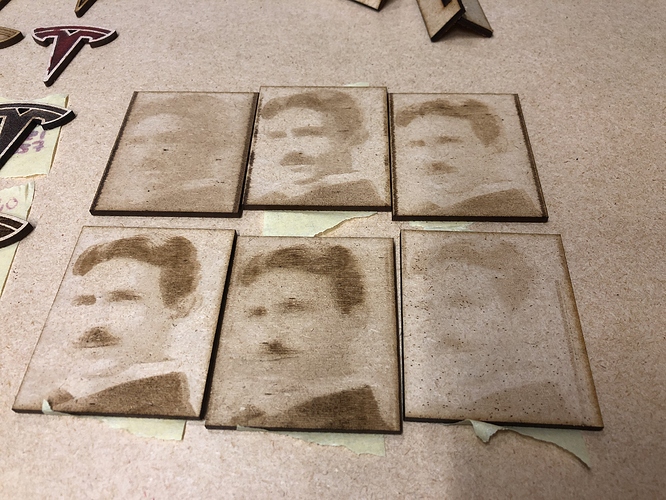
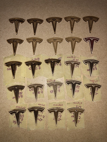
Ran some Teslas yesterday, slowly but surely getting there:

1 Like

I don’t see any drawbacks on using TH instaed of TL. That’s what it is for.

1 Like

It looks like the OpenDrain* configuration in Jim’s code is isolated and simple. Any reason you wouldn’t take a PR for adding it to grbl-LPC? Maybe adding OpenDrainB as well so all five stepper interfaces can be open drain?

Yes I would accept a PR, no problem.
The actual grbl-LPC is 4 axes only (XYZA), so OpenDrainB would not make sense.

Oh, right, was forgetting that upstream grbl has only four axes :slight_smile:

I remember seeing https://github.com/fra589/grbl-Mega-5X and forgot that it wasn’t upstream…

I have added a 4th, 5th and 6th axis to grbl-LPC (original grbl only had 3), but 5th and 6th axes didn’t work for some reason I don’t remeber, so I just commented it out :wink:

3 Likes

I modified from the original a bit to try to follow the style more closely.

Untested, because I bought the wrong board. :stuck_out_tongue: But it builds in either configuration. No pressure to take the PR based on lack of testing; at least if someone wants a minimal change against current master it exists now.

2 Likes

I see that you took the PR. I am… fortunate that the SKR board I bought, without realizing that it didn’t run grbl-LPC, seems to be defective and not booting their fork of smoothie either, so a return is trivial.

I wish they had used the same ports, since right now I’m just looking for an interface to some limit switches and a few steppers and don’t need 3/4 of the components on the board. I’m looking for cheap so I’m not invested and am happy moving to something better later without feeling like I’m throwing away a lot of money. Hopefully the sbase I just ordered, though stuffed with useless and terrible drv8825s that I will completely ignore, will work better and let me test my work.