EDIT: Whoops! Totally thought this category said “Hardware Conversations”, not “Hardware Conversions”. My bad!
Hey guys, I’m at a loss here with my DIY 40w laser cutter build. I’ve got GRBL 1.1 up and running on an Ardiuno UNO. LaserWeb3 controls everything great (including test-firing the laser), and if the laser is disconnected it’ll run the G-code that it creates for a part just fine. If you connect the laser, it’ll run for a variable amount of time before randomly entering an alarm state, losing communication via the COM port, or just freezing up. This happens with both LaserWeb3 sending the G-code and using the Universal Gcode sender, so it’s definitely something on the GRBL end of things. Has anyone run into this before? I’ve got experience with DIY 3D printers and lots of arduino experience, but this is something new & has got me stumped.
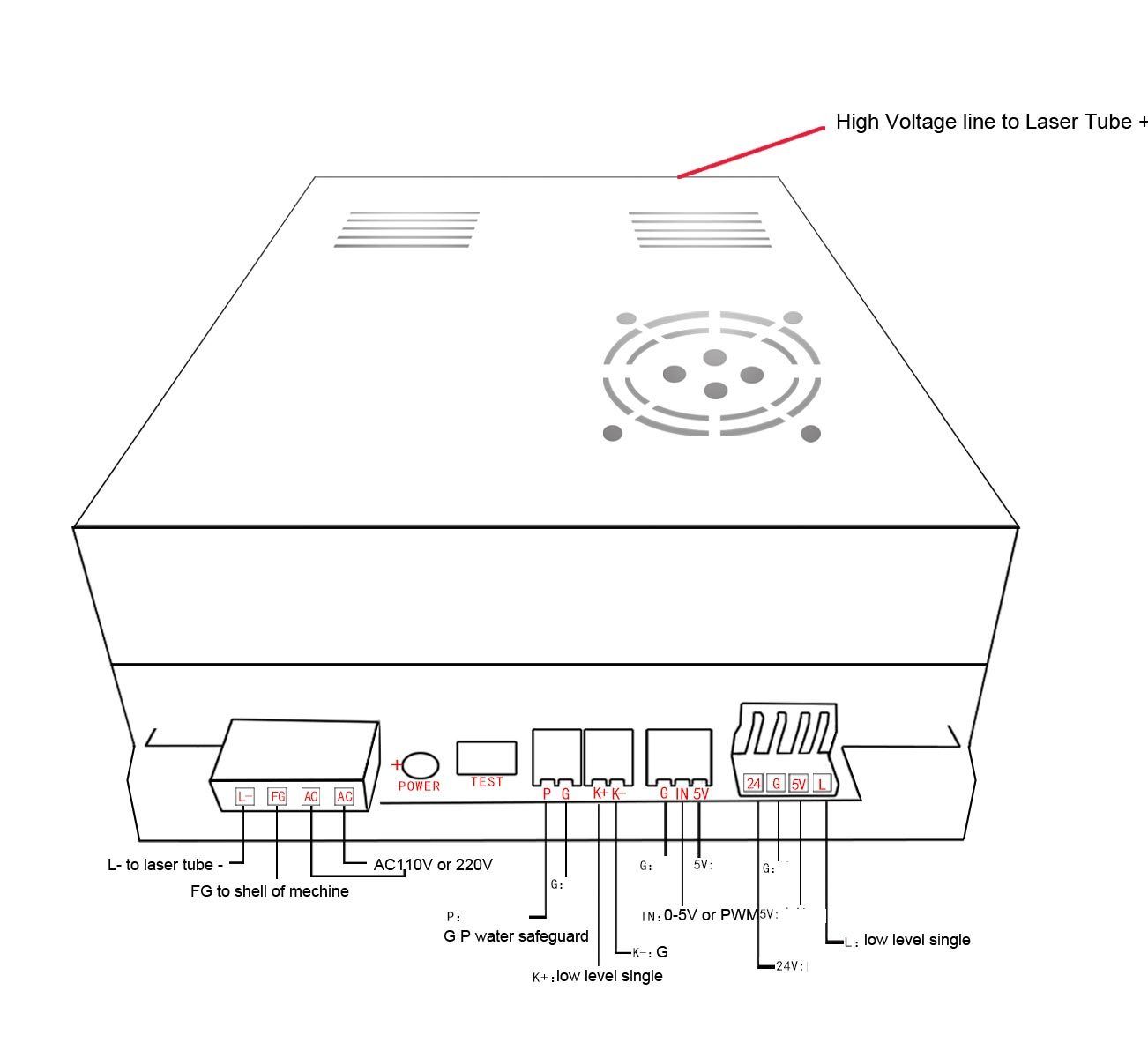
I’ve got the Arduino connected to the GND and IN connections of the laser PSU to give me PWM control over the laser, and I’ve got the “K-” terminal of the laser PSU tied to ground. I’ve uploaded an image that shows my PSU pinout.
The high voltage supply line to the tube is on the other side of the machine from the UNO, with the only wires that get near it being one of the stepper motor wires. I’ve got a common ground between the UNO, the laser PSU, and the motor PSU. Tried a couple of different cables that have worked well elsewhere. The chinese fake UNO is definitely a suspect at the moment - I’ve got a genuine UNO here at my apartment that I’ll bring back out to college with me this Monday.
Does the machine work ok before it goes into alarm, i.e. does it fire and mark ok?
Is there anything that happens just before the
Some considerations it does as +Peter van der Walt suggest sound like a noise problem:
Is the machine arching in any way. Arcs can easily cause electrical noise problems that cannot be eliminated, the arc needs to be fixed…
Grounding K- really shouldn’t do anything as K- is connected to ground in the supply. You can measure it with the power off to verify. What is K+ connected to?
What is P+, G connected to?
Is the gnd of the LPS DC connector solidly connected to the Arduino ground with a reasonable size and length wire?
The IN pin is connected to one leg of a differential amplifier in the LPS so depending on how you are switching the PWM from the Arduino that might create noise problems. Is the laser current POT still installed?
Is the laser cathode wired directly to the L gnd on the LPS AC connector (left).
Is the FG on that same connector solidly connected to the frame.
@donkjr thanks for the comment! I’m heading back out to work on the machine tomorrow evening, so I’ll double check some things and see where I’m at then.
Definitely not any arcing, all connections are good.
I remember getting 5v with reference to ground on the K- pin earlier today, but I’ll take another look at it tomorrow. K+ is currently just left floating, as I couldn’t actually tell that I was able to do anything with it.
P+ and G are shorted together for the moment since we don’t have any safety interlocks installed yet (just got the laser tube installed yesterday)
Dangit, it was at one point but I think I changed that. I’ll make sure to do that tomorrow.
Nope, I took off the pot when I connected the Arduino’s PWM output to it.
The cathode is indeed connected solidly to the L- on the left hand connector. FG is currently connected to the ground prong on the AC cable that I’ve got going to the LPS. There’s no enclosure on the machine yet, but once there is that’ll be connected there too.
Alright, just got back from another three hours session of beating my head into a wall hahah. Everything is properly grounded together. I swapped out the chinese clone with my genuine Arduino. All endstops are even unplugged. The only thing that I’ve got connected to the Arduino are the 2 Y-axis motors, the X-axis motor, ground, and the PWM output to the LPS. But still, GRBL/the Arduino randomly resets during a cutting job. Everything will be going great, until it stops and I get the boot-up serial message through the terminal. I did realize that I’m running GRBL 1.1e, while the latest is 1.1f. I’m going to try flashing that tomorrow and see if that magically fixes it, but I don’t have high hopes.
The only other thing that seemed a little weird to me is that the “IN” pin seems to be left floating, rather than pulled down. It was measuring roughly 5v with respect to ground. I assume that it’s just floating, but could there be an issue here that it was somehow backfeeding the arduino’s PWM output on D11 and triggering a reset? Seems absurd, but I’m out of ideas…
That’s definitely my thought too. The power going into the actual Arduino shouldn’t be an issue - that’s just 5V via USB from my laptop. I’m currently reading up on EMI issues and what we can do to mitigate them. What’s confusing to me is how I’m still having this many issues with EMI with hardly anything plugged into the board.
We’ve (my partner and I) tried two different USB cables now (one with ferrites, one without), but I’m bringing another to try tomorrow. I’ll snag some pictures as well.
@Alexander_Flick rather than radiated EMI, its likely you are getting a high speed shift in the ground or a power sag on the Arduino board causing a reset +Peter van der Walt suggestion above.
I would try these things:
powering the Arduino from some other source than the USB. BTW if your USB connection cannot provide enough dynamic power the voltage on the Arduino could sag.
add a filter to the Arduino’s power. This should not be necessary but maybe help pinpoint the problem. I would hang a 100uf and .1 uf cap across the Arduino’s DC supply terminals.
scope the arduinos DC supply. These may be high speed shifts so a good scope may be necessary but try whatever you have.
Frankly, I would not drive the IN pin with PWM, that said I don’t see how the interface to the IN pin could be causing this problem. How are you interfacing to IN from your Arduino. i.e. what port and how is that pin configured. I guess a load on the Arduino’s I/O pin could cause a sag on the processor chip. Try disconnecting the PWM from IN and run the job without firing the laser.
Today we stripped everything off the Arduino with the exception of the PWM wire signal and ground that runs to the LPS, and we swapped that one out with a shielded wire too (grounded at only one end). When we scoped this wire, it seemed like we were getting massive highspeed transient spikes (100v +) occasionally when the laser kicked on. I tried throwing an optoisolator in the mix to separate the Arduino from this noise, but that didn’t seem to make much difference (it was also at the end of 6 hours of testing, so the “Alex’s brain is toast” is always a factor…), so I guess that really does just leave the ground to be the culprit here. What’s the “ideal” grounding setup? I feel like I’ve tried them all at this point, but I’m still not getting anywhere.
I tried powering the Arduino with a separate power supply, but I’ve got a nicer PSU that I’ll try at another time to make sure that that wasn’t the issue. I’ll also add the filtering in place & use the scope to see what’s going on.
If I have a DC power supply for the Arduino, the UNO itself, the LPS, and my laptop, what should be grounded (I assume all of it…) and how? I know that sounds like an absurd question, and I promise I really do know what I’m doing - it’s just this EMI stuff that’s kicking my butt! Thanks for all the help.
PS: One thing I want to try is ditching the PWM input for now and just going to straight on/off control with a pot for power adjustment. That’s the next logical step in my “simplify it all until something works” trouble shooting method here…
EDIT: Hmmm, here’s another thing. Looking around, it seems people seem to be recommending a PWM frequency of 20khz… Grbl 1.1f by default uses 1khz. Does it make a difference? Guess I’ll find out…
But for my first Post i’d like to say a big THANK YOU to the Developers of Laserweb! Youre Awesome!
Before i ran a self modified Version of LaserSaur on Raspberry1 and Arduino Uno Clone with CNC-Shield. Everything worked fine. I added a dual SSR Board + 2x C13 Connectors at the back for M7 M8 control.
Then i switched to GRBL 1.1f and LaserWeb4, no issue noticeable in “dry-runs”
I’m not yet 100% sure what causes the strange behavior but i’d like to share some observations i made.
First tests (Rastering at low Power) seemed to work ok
Cutting at higher power gave me sometimes random unknown alarmstates or freezes, no complete Reset (i have still the POT@95% and PWM to IN of the Laser-PSU)
As i installed the SSR-Board today things gone worse. Dry-runs (Laser-Protect circuit open) performed well, but with the Test-Fire Button i can kill the serial Connection instantly!
When i hit Test-Fire during a dry-run, the serial Feedback of i.e. the Work-Position in LaserWeb or other Control Software freezes instantly. BUT GRBL is still moving till the Buffer is empty.
Soft reset is not possible
Hard reset (button on Arduino) resets the Arduino itself (can see the LED on Spindle-Dir blinking and hear the Stepper drivers “cirp” shortly. But Serial Connection is not possible. I even can’t disconnect/reconnect.
If bad things happen, only solution so far is to unplug the USB and replug again.
When enabling M7 or M8, my Air-Assist Pump is running, but barely sounds not 100% right (can’t describe). If i replace the Air pump with any kind of switching PSU, it won’t work correct in dry-runs. When everything but M7 M8 is idle, everything is ok, but i can cause strange behavior by hitting the Test-Fire button…
I switched back to my LaserSaur-Mod (same Hardware, no Changes besides replacing my Win-Laptop with Raspberry1) - No freezes, resets, … besides the Problem with the SSR-Board.
The only difference between my Firmware and GRBL 1.1f is the Baud-Rate of 9600 with very lightweight commands vs. 115200 with lots of traffic.
By the way, i also striped the guts of my Laser, disconnected everything, tried with external PSU. Even with everything outside the Housing (except one Y Stepper) with only Arduino, Laptop and external PSU connected i was able to reproduce the Issue.
Random thoughts:
Like you said, grounding/PE could be a reason, because everything is connected to the same outlet. I will check that with my Pocket Scope
SSRs may be to sensitive for this environment, try normal relay.
CH340 Serial-Chips (which worked flawlessly until now) may be the central part of the problem
I will speed up the baud-rate on my LaserSaur setup for further testing.
Clean up all the wiring may help
Insufficient power from my Laptop-USB-Port is another thing you make me think about.
Try to run GRBL/LaserWeb with my Linux-Laptop or raspi (would have been the next step anyway).
Correct the known bug in my diy PWM Level Inverter (add current limiting resistor)
Sorry for that long post and thanks for reading.
I hope we solve the issue rapidly…
@Alexander_Flick
Uggh … finding noise problems like this can be very hard.
This laser and power supply dump lots of energy 20KV @ 24ma in a very short time (ns) so grounding is important. Both radiated and conductive noise can be a problem.
…
My general rules for grounding are:
For PS: return ground back to their source and then the gnd of the all the supplies to a single point and the frame. This includes the ac mains ground.
In mine I added a 1/4" screw in the frame that I connect grounds with soldered ring tongue terminals and star washers.
i.e carry the ground to the endpoint but do not ground PS to the frame at the endpoint.
For sensitive signals use twisted pair carrying the ground with the signal. Typically ground at source and destination but sometimes leaving one or the other end open works.
Pay attention to the size of PS ground wires make them as big as practical.
Pay attention to connections, crimps are notorious sources of problems. I solder all my PS ground terminals.
** For your PWM signal I cannot make a recommendation because, unless I missed it, I do not know how you are driving IN from the Arduino.
Again, IN is typically the input to an op amp comparator that controls the LPS internal PWM.
…
Some K40 specifics:
Insure that the lasers cathode returns directly to the L- on the LPS and that the LPS FG is connected to the single point ground and the case.
Insure that FG, the case and the safety ground are connected.
…
I agree that its best to simplify the setup and connect disconnect things until you find the source.
I am unclear on exactly where you found the 100V spike. It reads like it was on the PWM signal. My guess is that it is actually on the Power supply.
…
I would disconnect everything, including ground, between the Arduino and the Laser power supply and run the systems to see if the problem is elsewhere or radiated.
…
FYI: the inputs on the LPS …already are opto-couplers assuming you have the typical K40 supply.
**Unless I missed it we do not have a picture of your laser power supply.
…
Scope the:
…DC power at various points including the Arduino
…Scope the Arduino’s reset circuit and its power source.
suggests to me that the HVPS is the source somehow the HVPS is injecting noise on the DC supplies.
Controlling 'IN" with a digital signal is not (by me) recommended. What port are you connected to and how is that port configured? I doubt the method of PWM connection is the source your problems but you never know when hunting for sources of noise.
3-7. HVPS noise as in #1
SSR’s should work fine in this setup but I suspect they are failing for the same reason as other electronics.
The aggregate of problems makes it sound like there is noise on the power system and impacting all electronics.
Its unclear in my reading if you have a configuration that works without noise or not.
I would start by disconnecting everything from the LPS, run and see if problem persists. If not start connecting things until you find the condition again.
things that could help us help you
a circuit diagram for your PWM connection and the Arduino’s setup of that port
@donkjr & +Peter van der Walt, thanks for the continued support! It’s nice to know that there’s people out there to help.
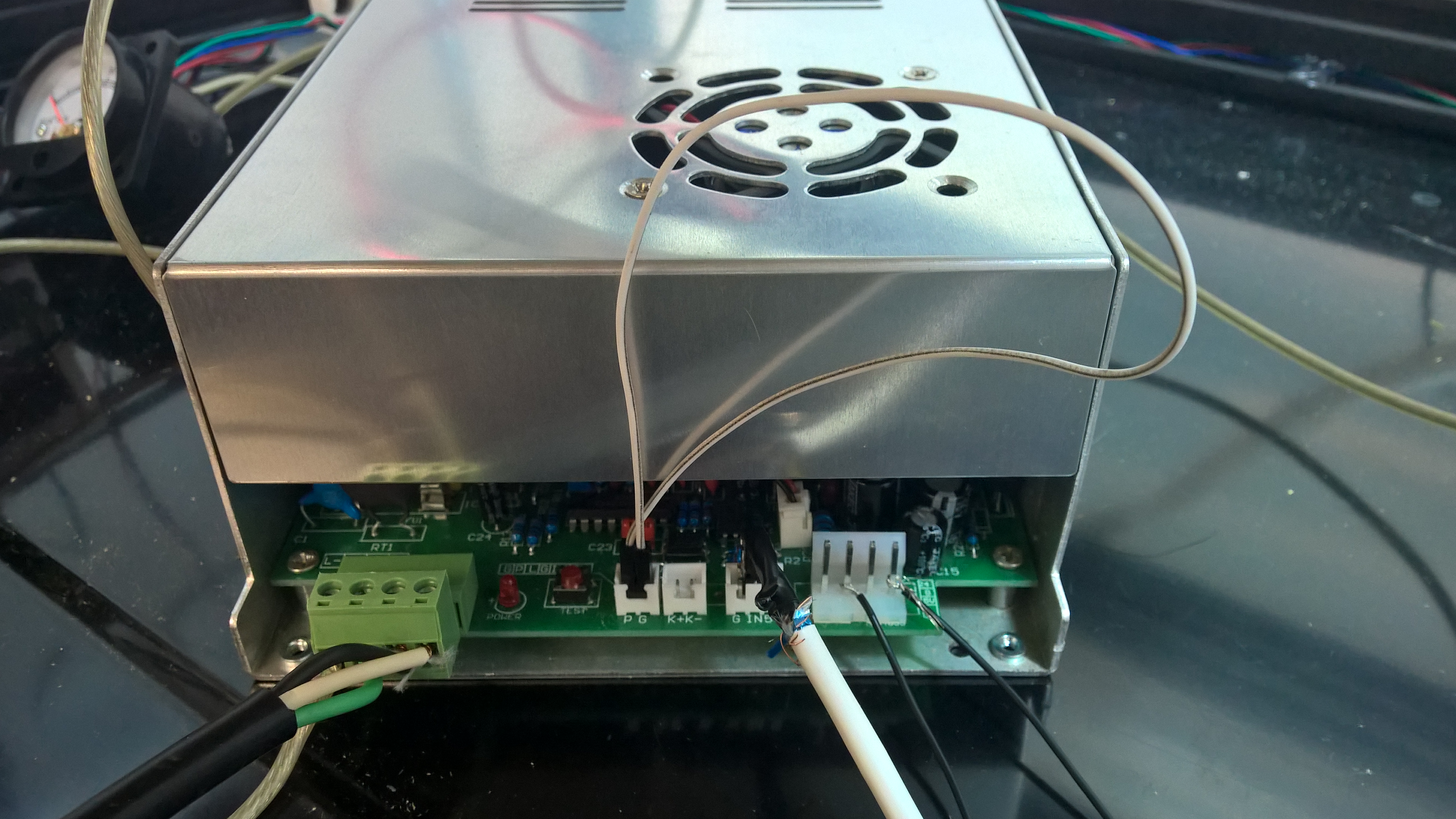
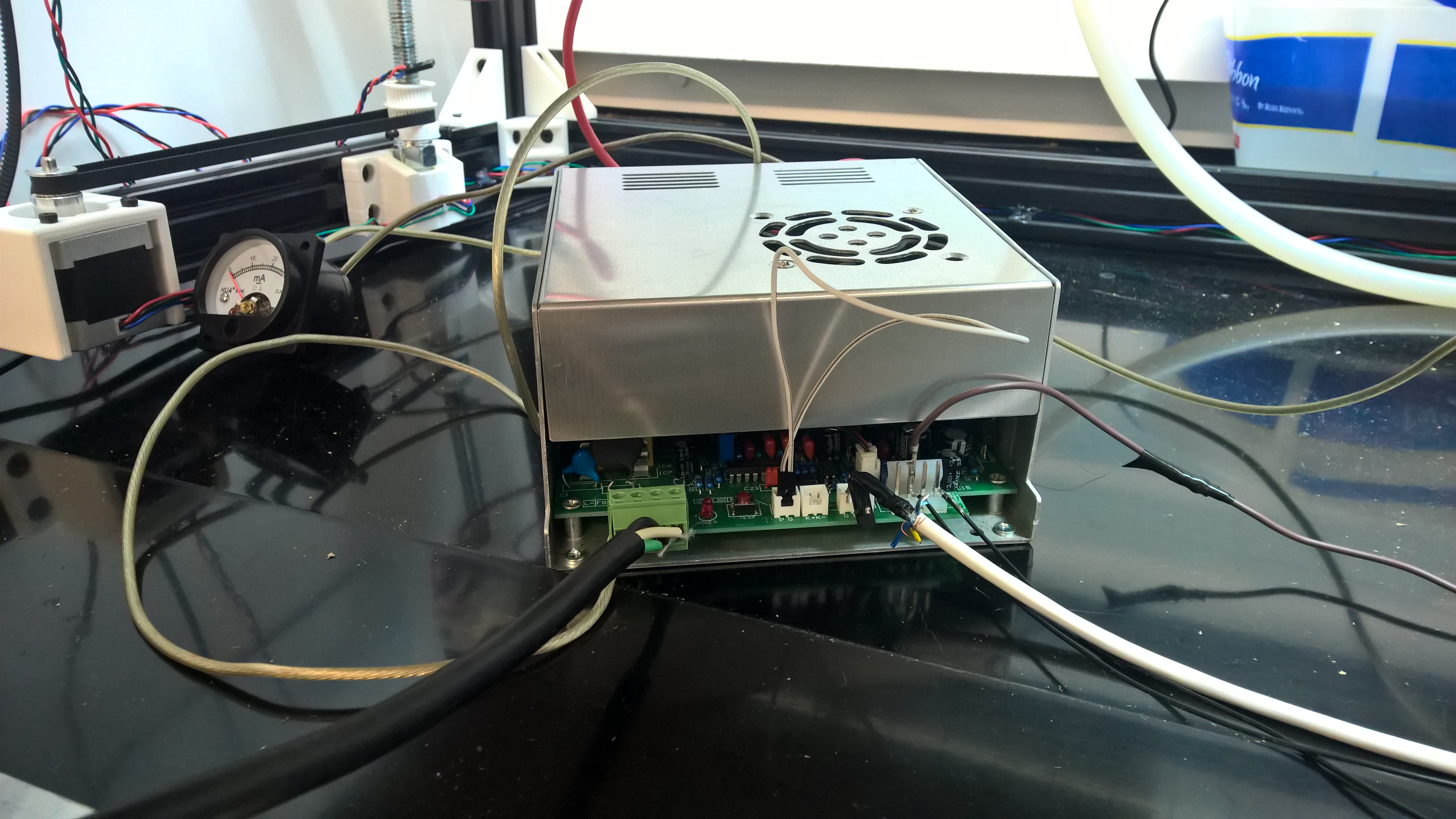
I finally(!) remembered to snap some picture of my PSU. It is indeed what typically comes with a K40. This is after I stripped most of the wiring away to tidy things up & start fresh once I get some time. As I mentioned earlier, P has always been shorted to ground (since there’s currently no safety interlocks), and the L pin (far right) has also been shorted to ground to enable the laser.
The Arduino is driving the “IN” terminal directly off of Pin D11’s PWM, which is the default “Spindle Enable” pin for GRBL 1.1. The large transient voltage spikes I was referring to were actually measured on this PWM line. I’ll make sure to double check this once I get back to it, but I was pretty confident that I measuring correctly. I’ll also make sure to scope the DC power and reset circuit.
@Alexander_Flick i suggest that first you need to get good connections all around. Wires twisted on terminals won’t cut it
Ground wires need to be good size and follow the grounding guidelines above including a single point that includes safety gnd.
The spikes on PWM I think is just illustrating that there is noise on the Arduino power buss.
Have you tried disconnecting the arduino from the LPS and running as suggested above?