Does anyone know if this Thingiverse design fits the 40W tube diameter?
That says it will fit tubes up to 55mm diameter. The sort of orange layer in contact with the tube is cork, he says he used 1/16" but you can use thicker (or multiple layers I suppose) to shim up for smaller tubes.
My tube measures 51mm, so you’d need an extra 2mm of cork, which would get you up to almost 1/8" total (assuming it’s 1/16" for a 55mm tube). I assume between the cork and the 3d print there would be enough give that the slight (0.5mm) overage wouldn’t matter.
Disclaimer: I know nothing about anything, listen to me at your own risk.
LOL – Thanks for the second opinion, @TwelveFoot  Interesting idea to just shim it up with more cork. Anyone think that’s a bad plan?
diy3dtech has made it so it fits the K40. see the videos on the thingiverse link.
I have that on mine but personally I think it would fit better if it was about 5% smaller. It’s very tight in the casing and there isn’t a lot of adjustment making it pointless IMO.
@Bob_Buechler interesting subject, tube mounts.
I planned to change mine to some decent mounts once the tube dies and I finally decide to rotate the tube to stop bubbles. I haven’t rotated it in fear that it will arc.
Then again I pondered is that really necessary since I will adjust this once and lock it down??
Perhaps we should do what I have seen one other do is make the entire tube and mount one assembly that is removable and adjustable.
This is an example of that approach.
@Andy_Shilling Anything is going to be better than the stock crap that is on mine now. I have no way other than to shim and bend the metal bands that hold it in place which mean I have to take it apart each time I need to adjust it. Most of my issues come from the case being thin and flexible. Funny thing is that I have one that is about 3 years old and the case is thicker and heavier than the newer one. In fact the newer one is so thin that they had to add stiffening supports on the bottom to keep it from flexing. The tube holder is also better on the older machine. One day I will build a better case. One day…
@HalfNormal the biggest problem I found with this was because it is such a tight fit I ended up taking the whole tray out to fit it but to do that i had to take out my bed and dividing plate between PSU and bed etc.
Royal pain and I would like to come up with something better at some point if I find time.
@Andy_Shilling thats why I am thinking that an acrylic sub plate like the video I posted, might be the best approach? You mount the tube on a plate that has adjustable mounts to get it parrallel and then the whole assy bolts into the frame. That way the tube is referenced to the plate not the freaky frame of the machine in two places.
I’ve become increasingly convinced that decent tube mounts will greatly simplify beam alignment by greatly decreasing the need to perform mirror alignments. As DIY3DTECH mentions in those Thingiverse videos, if everything is square, true 45-degree mirrors should be all that’s necessary. So true up the stock mirrors to 45 degrees, and perform tube alignment adjustments and mirror mount position changes from there.
I think I agree though that a position-adjustable bottom plate design that provides a small amount of vertical and horizontal play is the cleaner approach here. The tube would rest in a C-shaped cradle (open end facing up). Should be pretty easy to adapt the current Thingiverse adjustment wheel design to this idea.
I’m currently working on my own design. I’m hoping it will offer plenty of adjustment. The first test mount is printing now.
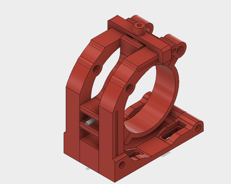
The small piece on top bridges both sides of the frame. Same thing goes on the side in front, but the picture doesn’t show it. A couple screws are bolted to the tube clamps and extend out so they can be used for fine adjustments. Nuts on the adjustment bridge ride on these screws and are use to adjust the tube on the 2 planes. The 2 larger holes through each frame will have a couple bolts through them to tighten the frame ends against the tube clamp to make everything solid. Then the adjustment bridge pieces can be removed, or just left in place. They will snap on and off and slide in the slots on the side of the frames. I have a couple frame pieces printed. They are small, but appear to be quite rigid. It should be very solid when everything is bolted together. There are some slots in the base to allow for some movement there. I may have to make the bottom base a bit shorter. I’ll have to see once it’s all bolted together.
@Steven_Kalmar Thanks for the details! I’d love to see some pictures when you have it all in place. I think that’d help me visualize the system a bit better.
I’m seriously considering buying these, since I can’t find a design like them on Thingiverse and I’m sadly not a 3D modeler. I’d love some community feedback though, especially if you’ve used this type of mount before: http://www.ebay.com/itm/CO2-Laser-Tube-Fixture-Mounts-Stand-Holder-Adjustable-Tube-Dia-50cm-60cm-80cm-/232211009500
@Bob_Buechler I have been watching this design on ebay but never found one of these smaller than 60mm so this one looks promising.
@Bob_Buechler I should have at least one of the mounts done this weekend, if not today. Depends on what I need to change. I’ll post it to Thingiverse when I’m done.
I considered purchasing those same mounts from ebay when I was designing a larger machine before I decided to learn on the K40 first. They look rather large for the very small space of the K40.