I’m sure we mean the same thing, but my digital meter jumps all over the place unless I use continuous pulse mode in the controller… The analog one doesn’t have this issue.
Didn’t think continuous pulse is possible with the K40 type wiring interface to the lps…unless you set power/pwm to 100%…?
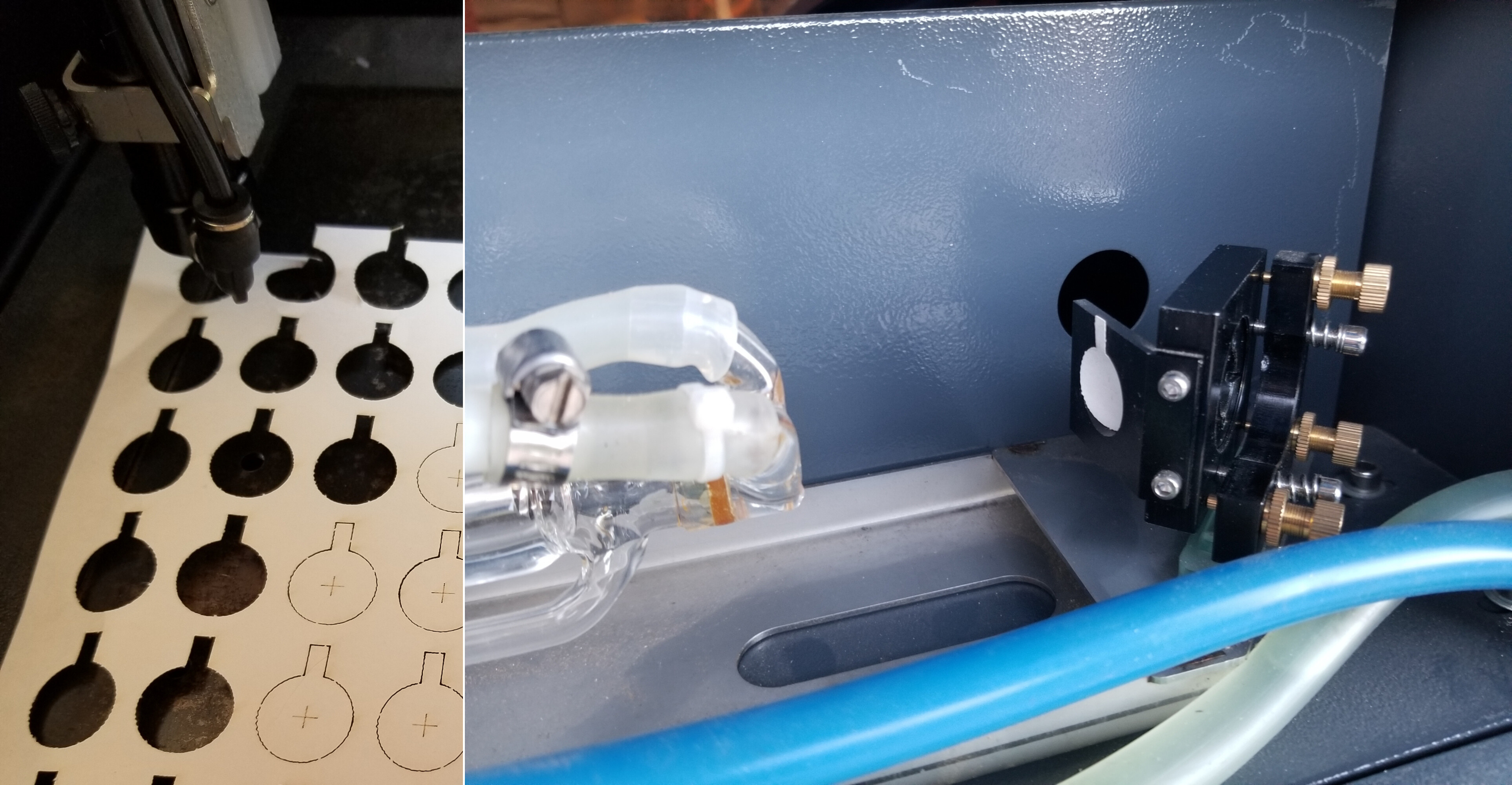
First thing I’d suggest is to ensure that the tube is working properly. Look at tubes output at M1 to ensure the tube is in TEM00 mode or resonance.
I use targets I’ve cut out for alignment… and how I test the beam at M1
0 - 30mA meters are common from China, can’t order from them? I got a couple of mine from Amazon.
I’d use the 100mA if that’s all I could get, your visual resolution will be slightly less than 1/3 of the 30mA meter. They are probably physically the same size, so you could swap it out when you locate a 30mA meter.
You can use a regular dmm, but it might give you strange results depending on your pwm settings. It again, is a digital meter that samples.
Make sure it’s connected well, if not, that cathode could end up having a high potential on it.
There is a rather large bubble in the photograph that I would think should have flowed out of the tube… Were you running coolant when the video was shot? If so, doesn’t look like much is moving.
If you are dumping frozen bottles in the coolant, it probably isn’t distilled water anymore. Just the contaminant from the bottles are not a good idea.
I had a copper coil that I used as a heat exchanger to isolate the coolant, until my chiller was working… I also put the exchangers pluming into a beer cooler that I can keep mostly shut, keeping in as much cool as possible.
In actuality, you broke a working machine… and didn’t get it to work again…
IMHO, I wouldn’t recommend you do a diy if you can’t get this one to work like it originally did… this one is probably >95% functional, a new diy will have 0% functionality when initially built.
The problem with changing tube power sizes is that they have different physical dimensions. A 40W tube is about 50mm in diameter and 60W is about 55mm and the 80W tube is 80mm in diameter.
You will have to raise/lower the tube supports or the optics (m1, m2 and the head) to change this… not to mention physical length.
In simple terms
- properly working tube
- clean and aligned optics
- proper focus
They work…
In the end, I’d say it’s most likely to be number 2… that is the most common issue that causes this.
Good luck