hi to all my board mks base 1.3 has abandoned i ordered a dlc32 2.0 to replace it you can kindly help me in connecting the pwm of the dell power supply i have some work to give and the machine is unfortunately unusable thanks in advance
What do you mean by;
How did you connect the PWM on the mks base 1.3 to the LPS?
Post pictures of:
Your controller and Laser Power Supply(LPS) showing the connectors?
the mks sbase is dead no longer turns on i need to know the pwm connections for the mks dlc32 2.0
Please answer all of the questions and post pictures.
Thanks,
Can you tell me how the other board was connected?
I will look this up tomorrow…
Derived from the information below and without knowing what firmware and how your previous controller was connected, connect:
- MKS DLC32:J17- [pin 1] to the LPS pin “Switch Laser Control (Active low)”
- Pick up a ground at J6- [pin 1] and connect to LP pin"Signal Ground"
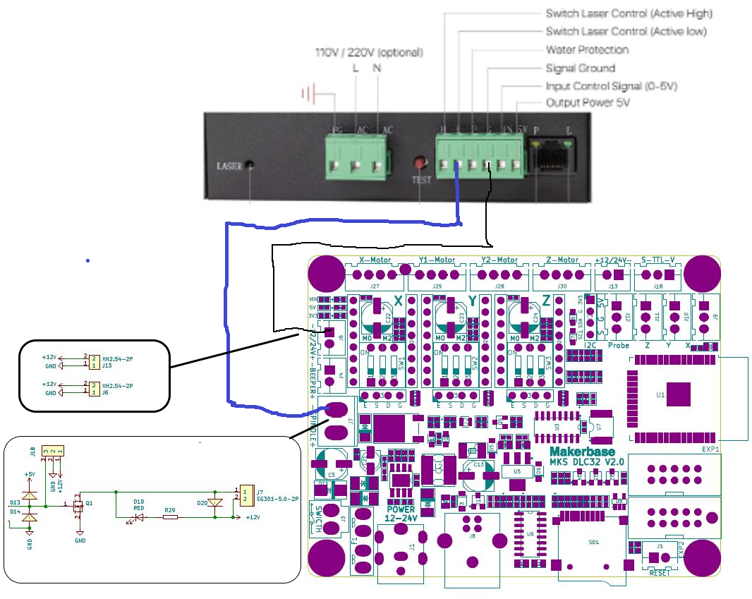
Check these things before you wire the controller:
-
With power on verify where 12/24V is on J17. It should be the side marked “+”. DO NOT CONNECT THIS SIDE. The other side marked “-” should be the correct pin to wire to the LPS.
-
With the power off, measure the resistance on J6- (minus) to a known ground pin to verify it is connected to the board’s ground.
I would use a twisted pair wire to make the connection.
In the firmware:
- The port on J17 must be set up for PWM
- Depending on the firmware used the PWM signal may end up being inverted
- Depending on the firmware used the PWM signal may not be able to be inverted and another solution may be necessary.
It would still be useful to have an answer to this question?
What firmware are you running?
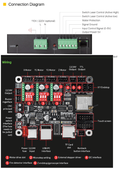
Information
MKS DLC32 V2.0_001 SCH.pdf (522.3 KB)
MKS DLC32 V2.0_001 PIN.pdf (76.0 KB)
1 Like
hello don I made the connections as you described to me the laser works all ok my only perplexity is that by connecting it to the spindle - and -24v the voltage that reaches the psu laser Is it 6.6v is there any way to get it to 5v? Can it create problems that is 6.6 or can I leave everything as it is?
Really thank you you were super nice and helpful
Can you tell me:
With what and where are you measuring the 6.6V?
What mode was the machine doing?
putting the test leads on spindle- and -24v the voltage and 6.6v with the laser off
- Did you verify that 24V- is the ground on the controller board?
- Disconnect anything on the 5V on the LPS. With power on read the LPS 5V relative to the LPS ground?
- In the same configuration as #2 what does the 5V on the LPS read relative to controller 24- (ground)?
- Disconnect the Spindle- wire from the LPS (blue wire in my drawing) with power on what does that open terminal on the LPS read relative to controller 24V-.(ground)