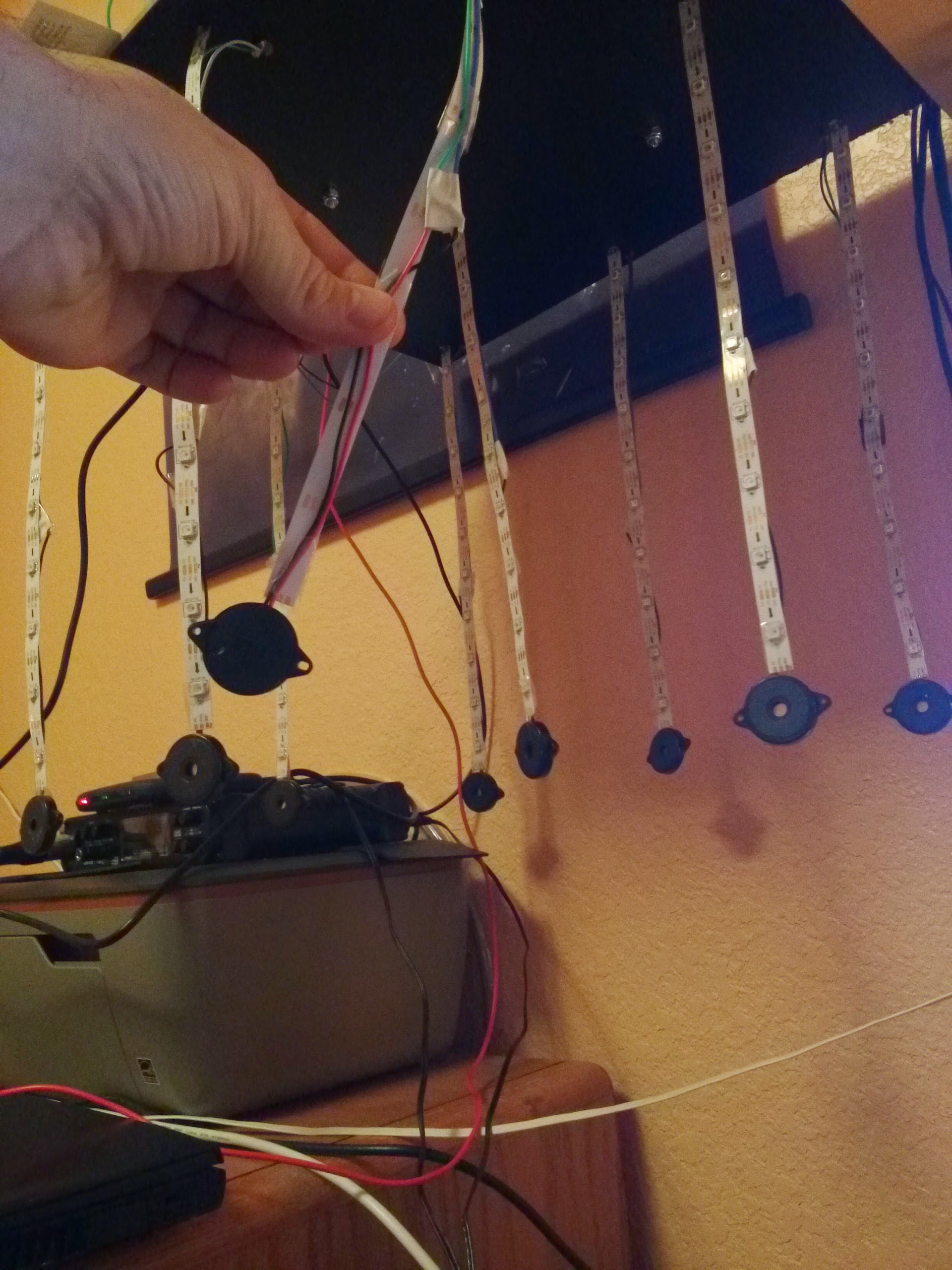
I’ve got led strips hanging down and at the end of each strip is a piezo knock sensor, with it’s wires taped directly to the back of the strip up to the mounting point where it goes it’s separate way.
When the led’s are off, the piezo’s work as intended, only showing fluctuation when tapped.
As soon as I plug in the led’s, the numbers jump a little erratically, jittering a lot but still responding which leads me to believe is a noise issue…
Would shielded 2 conductor wire solve this problem? Would that be enough insulation to block the electrical noise?
yes, i think using shielded cable will help greatly, as i think your long wires carrying the quite small current from the piezo element are picking up the data transmitted from the leds.
First… wow. This is an amazing project idea, and I can’t wait to see/hear more about it. At this point I can only imagine!
OK, so: I can think of two reasons why the lights being on might cause noise, the first is the one you mentioned, basically cross-talk from the adjacent LED strip, especially likely given that they’re side-by-side for an extended run.
The other question that came to mind though was this: How are you reading the sensors, and is it possible that there’s voltage fluctuation at the reading end of things? E.g., if you’re reading them with a microcontroller’s input pins, and that microcontroller is on the same power supply as the LEDs, then maybe the fluctuations in the LEDs’ power draw are causing fluctuations in the power being supplied to the microcontroller, and that in turn is causing the microcontroller to give fluctuating readings even when the input is unchanged. I believe that microcontrollers try hard to isolate this sort of thing from their “analog input” pins, but I suppose it’s possible that there’s something going on here.
I think for simplicity, I’d try shielding the piezo’s wires on one of the strings and see if it helps. If so, you were right, and you have a solution. If not, maybe experiment with separating the LED power supply from the MCU power supply?
Thanks for the comments! I did try moving the power supply to another source for reading the piezo. No change! So yeah it looks like a noise problem. I never thought about the fact that the piezos are dealing with such low current that they would be more susceptible.
I’ll try the shielded cable out and and let you know how it works!
I’m kinda worried for the full project since each piezo will have anywhere between 12 -24 feet cable run in a 4conductor wire along with the LEDs…
I guess my other option is to have a small MC like a trinket, something low cost to read the piezo value and send it back via boosted signal?
Or would it even work that way?
Well, if you just want to boost the signal, you don’t have to use an additional MCU, just a couple of transistors (possibly even just one) and a few resistors, but I don’t know how long your line back to the MCU is, and some calculation may be required. If you did use a local MCU to detect knocks, then even its signal back to the main controller would suffer from induced noise. That’s why midi uses opto isolation, and DMX and RS485 uses balanced lines. Long data lines, even at modest speeds are a PITA.
If its very long (more than say 5 feet), then as it stands, it may currently be able to detect light switches being turned on and off, and even lightning… Ha, that’s just given me an idea!
So, to sum up, If you must/need to have long runs, then induced noise will be an issue, and your desgin we have to compensate for that, amplification will likly only be part of the story.
Let us know your thoughts, its an interesting project indeed.
Thanks I really appreciate the detailed thoughts on the matter.
This is for an upcoming interactive spatially mapped led art installation, and right now I’m in r&d phase, but there will be 2 meter (30 per meter) hanging led strips with varying cable runs but the LONGEST there will be is 15 feet.
So, 6.5 feet of tubing run along the led strips + 15 additional feet max. So worst case about 22 feet of wire…
I’ve already tested shielded two conductor a few minutes ago and that definitely remedies the interference problem.
The other issue is the one I’ve been dreading and the one you’ve explained in more detail about the integrity degrading over long runs…
I can confirm that this works at about 8-9 feet just fine from a test a few days ago, so I will try a full 20-25 foot run and see what it turns up!
Could you elaborate on the transistor concept or point me to any good reading material on doing amplification for this sort of thing?
That could be a great plan b, also a plan c would be a lot more expensive, but and MCU in the end of each strand, with a wireless nrf24l01 connected to each communicating back to a base station arduino receiving all the wireless knock values… Sounds like a barrel of problems of it’s own though.
Designing with piezoelectric sensors Piezoelectric sensors require some precautions when connecting to sensitive electronic components. First and foremost, the voltage levels created by hard shock can be very high, even around 100-V spikes.
More than likely, an op amp will be used to interface these sensors to an A/D converter, either discrete or on a microcontroller. One tip is to choose a high-input-impedance op amp to minimize current. One possible candidate is the Linear Technology JFET input dual op amp. It has 10¹² Ω input resistance and a 1 MHz gain bandwidth product, good enough to easily handle the vibration ranges of piezoelectric sensors.
Another suitable part is the TLV2771 from Texas Instruments. This rail-to-rail low-power op-amp also has a 10¹² Ω differential input resistance and a 5 MHz unity-gain bandwidth. Signal conditioning in a single stage can prepare the input from the shock sensor directly into an A/D converter.
Op-amp circuits can be designed to operate in voltage mode or charge mode. Charge mode is used when the amplifier is remote to the sensor. Voltage mode is used when the amplifier is very close to the sensor.
Your long unshielded wires are forming a random length wire antenna, ham radio operators use these in some cases to talk around the world. If the wire length is right, it will resonate at certain frequencies and pick them up very well. Shielded wire is the way to go, and ground the shield to earth ground if possible…
Thanks you guys, picked up 30 ft of shielded 18 and 22 awg 2 conductor. trying that first before delving deeper into any alternatives in the hopes that works!
i’m not very good with AWG (i’m from the UK), but from working with pixel strands that claim to be 18 AWG, i’m thinking, that could be quite a bit bigger than you can get away with. Also you should be able to use single core screened cable. I’m telling you this as it may be a factor in the aesthetic of your installation.
I’ve sketched up a schematic to show a knock sensor using a jfet transistor to provide a nice clean pulse for each “knock” - its adjustable too, to help with noise rejection. But i can post images in comments (Boo Google+).
And, while I remember.
While piezos can generate big spikes, looking at your photo, and what you describe, I don’t think you will have to worry about them generating 100v spikes, but that can be protected against.
With those units in your photo, you will see about 2v for a 60g shock.
1 megaohm resistor between +/- near the knock sensor
Connected directly to my breadboard and the teensy 3.1
uncoiled the wire completely
The quality of the knock is as good as other ones with short runs!
Amazing, I definitely didn’t expect the signal to stay intact so well.
I’m using these piezo knock sensors from adafruit:
Thanks for the help Stuart! Fingers crossed but I may be able to keep things simple and just run this wire. I wont be needing 30 feet either, closer to 21.
In case you were curious, the project is an idea I’m getting ready to pitch to a few music festivals this summer, this was more or less the last kink to work out in terms of R&D
As noted by others the LED strips act as an antenna for the pulsing data/clock signals, and having a second cable running in parallel with high impedance signals will give you very good noise coupling (crosstalk).
Make sure you test the noise levels with rapidly updating LED patterns like you expect to have in the final installation.
Most people don’t realise how much noise is generated by the clock & data signals in these LED strips. Not only are they acting as antennas, the signals are regenerated by each IC/LED along the strip making the antenna more effective. The sharp edges of the square waves generate strong harmonics at much higher frequencies.
I’ve gone through EMC (FCC) certification for a WS2812 based product, and this was quite a pain point. I suspect very few installations actually meet FCC regs.