A sampling of the variation that I see in my “curtaining”

It’s pretty obvious when you cut timing belt with steel cords in it, so you would have noticed. Less likely for fiber cords to have broken. That’s probably a red herring, sorry! I’ll go back to lurking…
1 Like
If this is plywood you are using then engraving too deep will get you into other layers in the wood which can produce some strange artifacts.
1 Like
make sure there is absolutely no slop in the lens tube and make sure the lens is held in place with an o-ring with a little pressure on it(so no wiggle).
If everything is tight, I would start looking at firmware settings or drivers to see if there’s any accelleration limiting going on and causing the oscillation.
The sine wave thing is odd but as was mentioned, it is likely in the wood since it does not show up anywhere else. I would also troubleshoot this using a standard rectangular engraving instead of any design so consistency can show effects of changes better.
2 Likes
Thank you everyone for jumping in, I really do appreciate it. This community is awesome.
@dougl I cleaned my lense and check the o-ring to ensure it was secure.
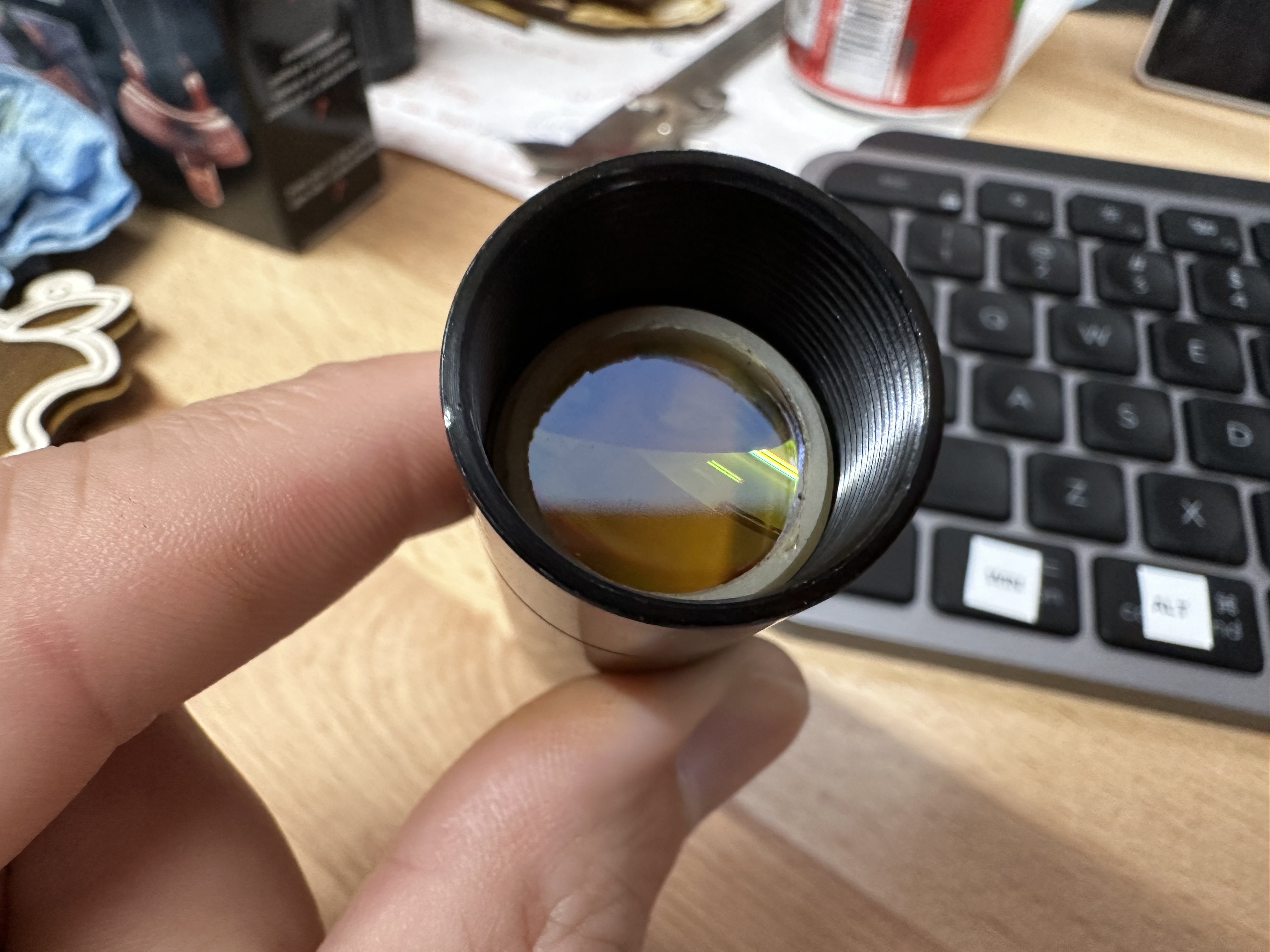

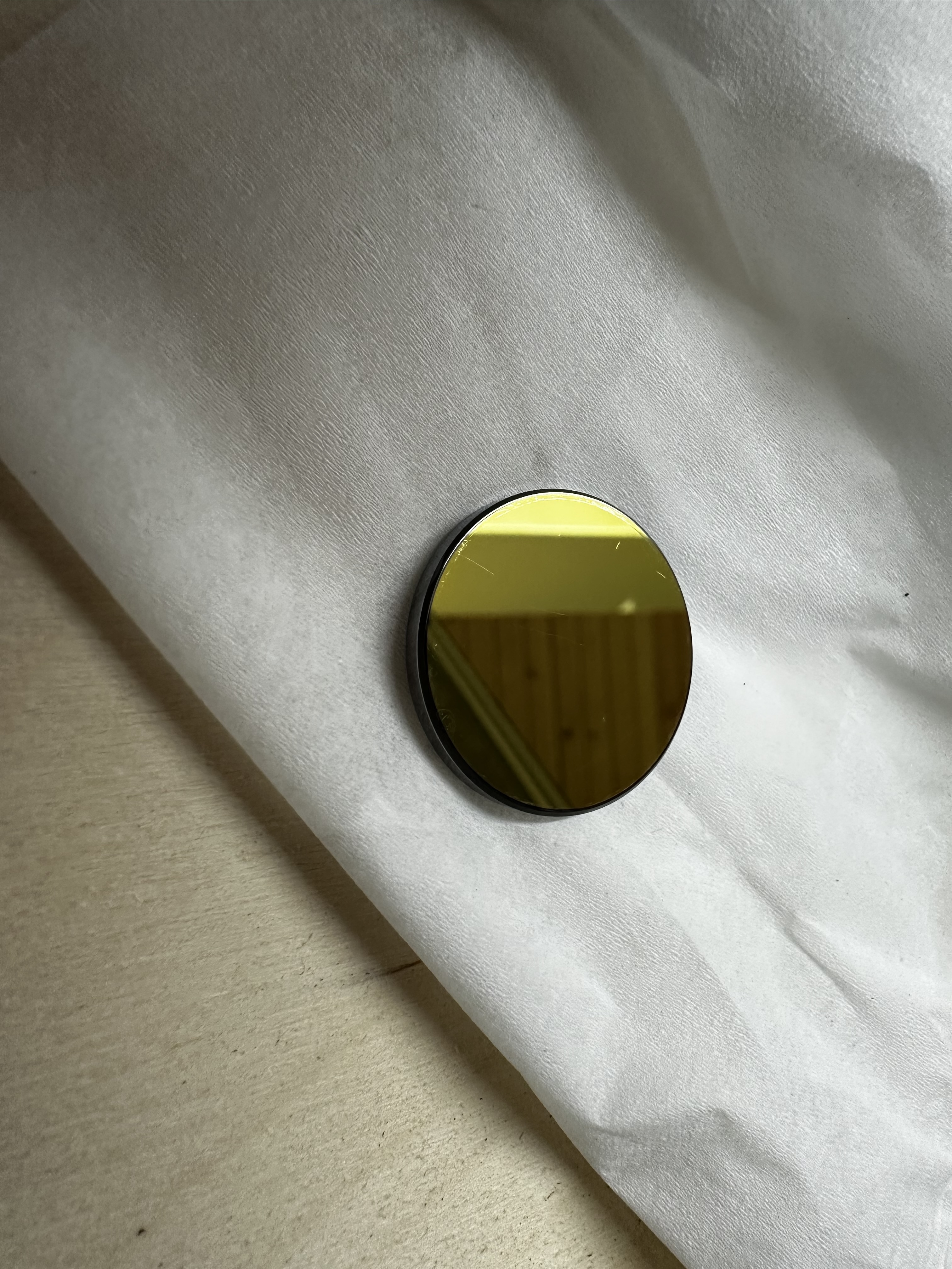
Everything is as secure as it can be. I have a K40, my first laser, and that thing is wobbly. I mean how can this flimsy piece of metal hold that mirror stable?? The K40 doesn’t have this type of pattern going on. What an amazingly cheap piece of tech that just works.

Here are the settings I have setup for FluidNC.
I don’t think my acceleration values are out of the question. As a matter of fact, the image in one of my prior posts that I engraved on pine (just a square) I had adjusted the acceleration down to 1000 mm/sec2.
Sorry for this, the forum wouldn’t let me upload a text file???
name: "TMC2209 XYZ  Laser"
board: "FluidNC 4X 2209"

stepping:
  engine: I2S_STATIC
  idle_ms: 255
  dir_delay_us: 1
  pulse_us: 4
  disable_delay_us: 0

axes:
  shared_stepper_disable_pin: NO_PIN

  x:
    steps_per_mm: 200
    max_rate_mm_per_min: 18000
    acceleration_mm_per_sec2: 3000
    max_travel_mm: 750
    homing:
      cycle: 1
      mpos_mm: 0
      positive_direction: false
      seek_mm_per_min: 3000
      feed_mm_per_min: 240

    motor0:
      limit_neg_pin: gpio.36:high
      limit_pos_pin: NO_PIN
      limit_all_pin: NO_PIN
      pulloff_mm: 5
      tmc_2209:
        uart:
          txd_pin: gpio.16
          rxd_pin: gpio.4
          rts_pin: NO_PIN
          cts_pin: NO_PIN
          baud: 115200
          mode: 8N1

        addr: 0
        r_sense_ohms: 0.110
        run_amps: 2.0
        hold_amps: 0.500
        microsteps: 32
        stallguard: 0
        stallguard_debug: false
        toff_disable: 0
        toff_stealthchop: 5
        toff_coolstep: 3
        run_mode: CoolStep
        homing_mode: CoolStep
        use_enable: false
        direction_pin: i2so.1:low
        step_pin: i2so.2
        disable_pin: i2so.0

  y:
    steps_per_mm: 106.67
    max_rate_mm_per_min: 12000
    acceleration_mm_per_sec2: 1500
    max_travel_mm: 410
    homing:
      cycle: 1
      mpos_mm: 0
      positive_direction: false
      seek_mm_per_min: 3000
      feed_mm_per_min: 240

    motor0:
      limit_neg_pin: gpio.39:high
      limit_pos_pin: NO_PIN
      limit_all_pin: NO_PIN
      pulloff_mm: 5
      tmc_2209:
        addr: 1
        r_sense_ohms: 0.110
        run_amps: 1.800
        hold_amps: 0.500
        microsteps: 32
        stallguard: 0
        stallguard_debug: false
        toff_disable: 0
        toff_stealthchop: 5
        toff_coolstep: 3
        run_mode: StealthChop
        homing_mode: StealthChop
        use_enable: false
        direction_pin: i2so.4
        step_pin: i2so.5
        disable_pin: i2so.7

  z:
    steps_per_mm: 400
    max_rate_mm_per_min: 200
    acceleration_mm_per_sec2: 25
    max_travel_mm: 200
    homing:
      cycle: 2
      mpos_mm: 0
      positive_direction: false
      seek_mm_per_min: 200
      feed_mm_per_min: 100

    motor0:
      limit_neg_pin: gpio.34:high
      limit_pos_pin: NO_PIN
      limit_all_pin: NO_PIN
      pulloff_mm: 4
      tmc_2209:
        addr: 2
        r_sense_ohms: 0.110
        run_amps: 2.000
        hold_amps: 0.500
        microsteps: 16
        stallguard: 0
        stallguard_debug: false
        toff_disable: 0
        toff_stealthchop: 5
        toff_coolstep: 3
        run_mode: StealthChop
        homing_mode: StealthChop
        use_enable: false
        direction_pin: i2so.9
        step_pin: i2so.10
        disable_pin: i2so.8

spi:
  miso_pin: gpio.19
  mosi_pin: gpio.23
  sck_pin: gpio.18

i2so:
  bck_pin: gpio.22
  data_pin: gpio.21
  ws_pin: gpio.17

coolant:
  flood_pin: gpio.25
  delay_ms: 5000

Laser:
  pwm_hz: 5000
  output_pin: gpio.26
  enable_pin: NO_PIN
  disable_with_s0: false
  s0_with_disable: true
  tool_num: 0
  speed_map: 0=0% 500=50.000%
I would be slowing things down and testing to see when it starts. Also would be feeling or listening(wood dowel on frame and ear while it’s running) to see what’s up. Maybe put a mic on it and record then look at the sound on a fft display in a sound file editor.
All after I looked at each and every part of the laser path.
AS for the K40, it can hardly run over 150mm/s stock so it seems that is rigid enough at those speeds. Add a bunch of upgrades(Russ Sadler) and you can get 800mm/s but only scanning along X axis and upgrades include better mirror mounts and MUCH lighter laser head.
1 Like
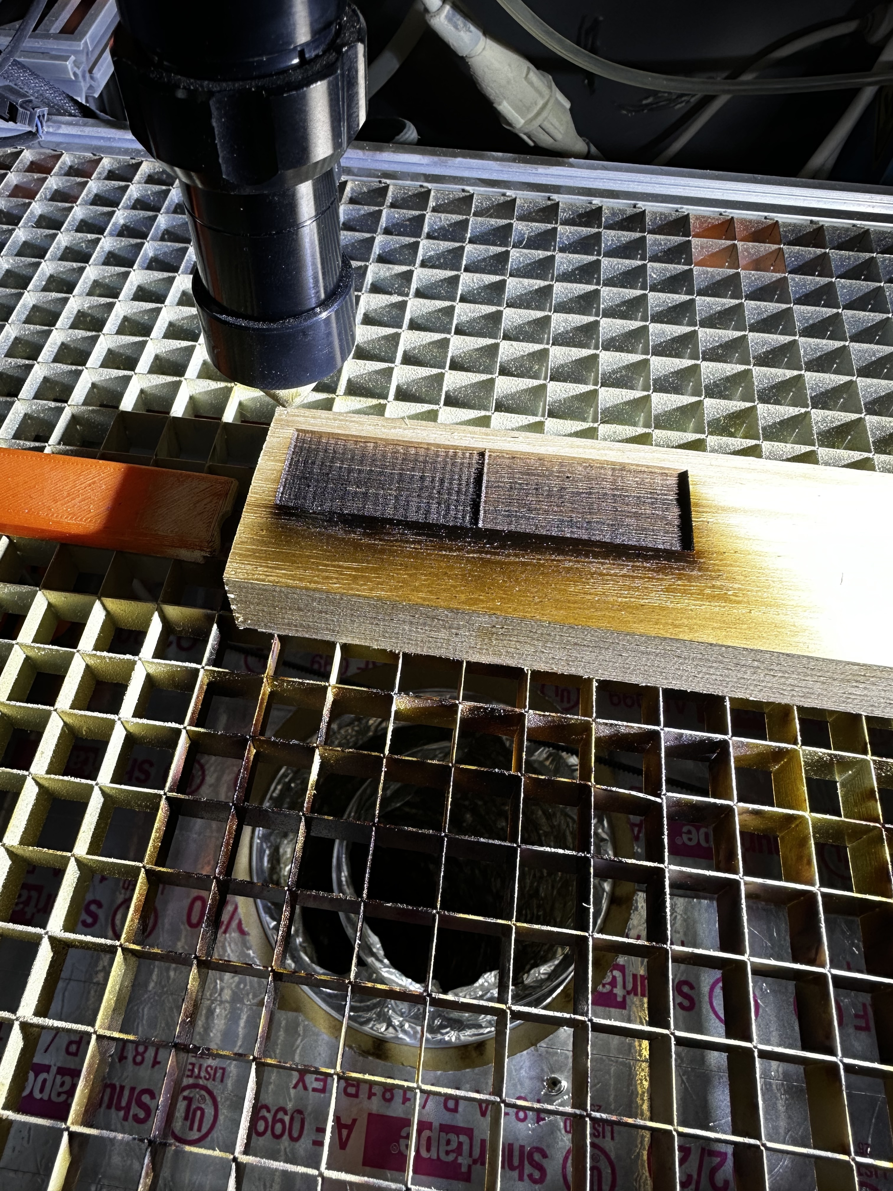
I took my speed down to 60mm/s and acceleration to 500mm/sec2. This is really really slow compared to where I was at. The pattern is still there.
I was running a plain square job to see the results. I did end up running the job a few times with the laser off so I could feel around and look around. At one point I put my hand on the second mirror. It is a very low hum on it. This is was made me turn the speed and acceleration down. I can’t imagine that mirror ever being entirely separate from the x axis as it must move with it to bounce the beam.
I bought a cheapo diode laser and have been thinking about mounting it to the x axis and burning some squares. This would help me eliminate the mirrors as a source of the problem. If the pattern emerged with the diode, then I could say it’s not due to the 2nd mirror vibrating.
Any thoughts on how to isolate the 2nd mirror from the x axis’ motion system and the resonant frequencies it creates?
A strange observation. In my new laser, I call the big laser, the plasma beam that I see formed inside of the tube randomly changes orientation as it blasts out the end of the tube.
I fired up the k40 just now cause I have orders to fill and I decided to watch the laser tube. I attached a video that shows fairly consistent beam formation, very different from the big laser.
You might be testing with the same file but the controller firmware are very different and therefore what the laser is doing is going to be different. But you might have found that the firmware on the big laser is what’s causing the problem. A common firmware might be enlightening.
I have had the same hardware on both the big laser and the K40. An Arduino Uno with CNC Shield running GRBL. With this setup, the same issues arise…
Let me put it another way, since you are using buffered type firmware and they are not the same, comparing what one firmware is doing at the laser to another firmware isn’t going to tell you much when you see variations.
But if that is indeed true, ie it was doing the SAME banding marking when running the same GRBL firmware then it’s the hardware or maybe the LPS. There have been some odd things happening with some LPSs in certain power ranges( usually low teens ).
Can you point to some more information about the odd behavior of the LPSs? I’m leaning hard towards the laser and laser power supply
after finding it I was reminded it was spotting throughout the engraving, not the banding you are seeing. Laser glitching around text
Frankly, I’m quite surprised you are seeing the same results at fast(200+ mm/s) and at slow(~50mm/s) speeds. Seeing the same period/spacing of the bands at different speeds, AND when you had the belt inverted just doesn’t sound right.
The spacing of the bands does change with different speeds. You can see that in the image I posted above (quoted below), apologies if I was not clear on that. Now what does not seem to change anything is inverting the belt. I did at one point have the GRBL controller connected to the big laser, it was displaying the same symptoms as the FluidNC controller. I swapped them because the guys developing the FluidNC software had a devastating bug with the Espresiff SDK and I was suspicious.
When I look at the picture below, all I see is a reflection of the GT2 belt pattern. It is damn near identical…
Somehow I must have missed the important fact that the pattern does change when you change speed. When I mentioned running at different speeds I thought you just said it still does the banding and nothing more.
Did you measure the spacing of the bands at different speeds to try and determine a correlation between speed and banding period? And I’m sure you know that as you change speed you also have to change power so that you’re getting the same amount of power dumped into each pixel.
It would also be helpful to provide the link to the post with the image instead of creating a low resolution image of a previous post.
I did not provide explanation. It’s not your fault, its mine. I did say “it still does the banding”. It does seem like the banding changes with speed, besides the images I have provided, I have no empirical evidence that shows the actual speed associated with the images I have posted. I will make a few burns tonight and associate them with speed and power settings. I will then make another post so I can provide more concrete evidence of what is happening and at what speeds and powers.
Here is a link to the post so you can see the high quality image:“Curtains” in engravings - #11 by James_Harding
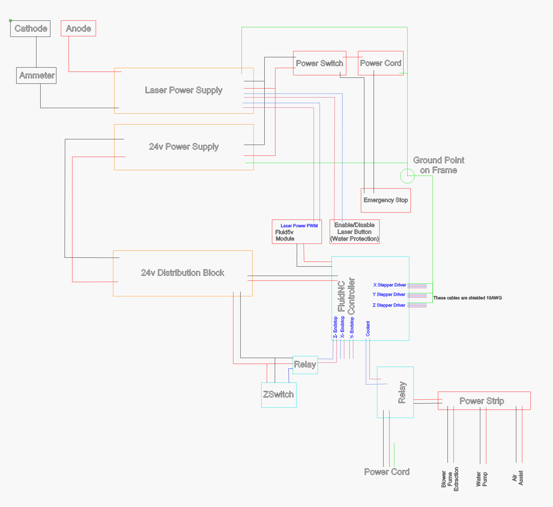
Varying with speed makes me wonder about how you are managing laser power. I don’t think you have shared a schematic with us?
Are you using an analog pot to set the max power, so that you can use the full range of digital PWM? If you aren’t, then you are using only a small portion of the 8 bits of PWM duty cycle, and I think you could end up with aliasing like this. This would be a difference from the K40 where you would be using a larger proportion of the digital range, and thus see less of an aliasing effect. I’m just listing one thing that could be related here, could be something else.
In any case, it’s worth listing all the components you used in the big laser with a schematic of how they are connected.
1 Like
Judging by these comments, and my own experience, I would check the idler wheels riding the aluminum extrusion for nicks or out-of-round. I built a custom laser machine myself and had the same problems. Turned out it was the delrin wheels. Some were out-of-round, which would cause an oscillating pattern length equal to the circumference of the wheels. Also, when you load the gantries on to the extrusions, the sharp edges of the aluminum can pit the face of the wheels causing a repetitive disturbance in the motion.
1 Like
No, I am not using a pot. The K40 is also not using a pot.
Parts:
Laser Power Supply: Cloudray
Laser: Cloudray
Lens: TEN-HIGH
Mirrors: Amazon
Laser Head: CloudRay
Laser Mount: Amazon
Y-Stepper: Amazon NEMA 17
X and Z Steppers: Stepper Online NEMA 17
24v Power Supply: MeanWell
Z-End Stop (Auto Focus): CloudRay
Z-End Stop Relay: Amazon
Power Strip Relay (exhaust, water pump, air assist): Solid State
V-Slot Wheel: Amazon
Smooth Idler Pully (x and y axis): OpenBuilds
Nut Block for Z Axis: OpenBuilds
Lead Screw for Z Axis: OpenBuilds
X Axis Belt: Amazon 9mm w/ 16tooth pulley
Y and Z Axis Belts: Amazon
Shielded Cables for Stepper Motors: Amazon
Exhaust Blower: Amazon
Water Pump: Amazon
5v Output Module FluidNC: Bart Dring
FluidNC Controller: Bart Dring
Nuts Bolts and miscellaneous hardware all came from Openbuilds
Surely there is more, if you have something in particular, just ask and I’ll find where it came from.
Here is a schematic of the current setup: