I’ve tried doing some searches before I posted this, but nothing seems to be covering this specific topic. The gantry that manages the X axis (left to right) of the machine I’m currently using is a bit skewed (looking into the machine, the right side is positioned slightly closer to me than the left side when the machine is off. This being the way that it is, when I cut or engrave something, the right side of the object(s) are lower (closer to me) than everything on the left side. What is the best course of action to align the actual bar that the head travels across so that this is properly aligned? This also affects my ability to properly align the lenses, since proper alignment on the left side of the Y axis has been fine, but the top right and bottom right corners have been difficult to compensate for since the bar is skewed. So not only are the objects I cut out misaligned, but the items on the right are not cut as clean as the left. And the size/shape of the stuff I cut out is consistent/correct, so if I cut a circle, it IS round as opposed to ovular, so the problem is only the X gantry. How can I fix this?
Are you familiar with the belt tensioning system on the actual gantry? Where the pulley is mounted on the right side there is a screw that you can tighten/loosen to adjust belt tension. There is in fact 2 more I believe on the left and right lower beams for the 2 belts that drive the gantry forward and backward. These are located in the back kinda under the laser tube and are a pain to access. It sounds like the gantry itself is not positioned the same on the 2 belts and that one side needs to be shifted by a few teeth. I would loosen one side, “skip” a tooth or two and measure the distance from the front wall to the gantry on both sides. When your satisfied, re-tighten the tensioner and re-measure to ensure it didn’t shift on you.
Alternately you could loosen the set screws on the rod=stepper motor connection but I personally avoid that as I don’t want to have a chance of those coming loose while running/stripping out/etc. Make sense? Hope this helps 
Working on this now to see what I can figure out. I am not familiar with this at all, but I am now making myself familiar with this. Thank you for your input.
After further inpsection of that part of the machine, I’m not quite sure which screw I’m supposed to be tightening. including a pic of the area I’m confused about. the belt tension on that side is actually pretty bad, so it is totally possible that tightening the belt is necessary, though I can’t tell if that will be enough to properly align the gantry. Could something else be the reason behind it being off by a couple of degrees? Including a picture of the gantry from a top-down view so my point is better understood. Starting a search online for a better view of that area where the belt is connected to the gantry as well so I can see exactly what I need to move and how. If anyone can provide pictures, that would be phenominal. Thanks in advance!
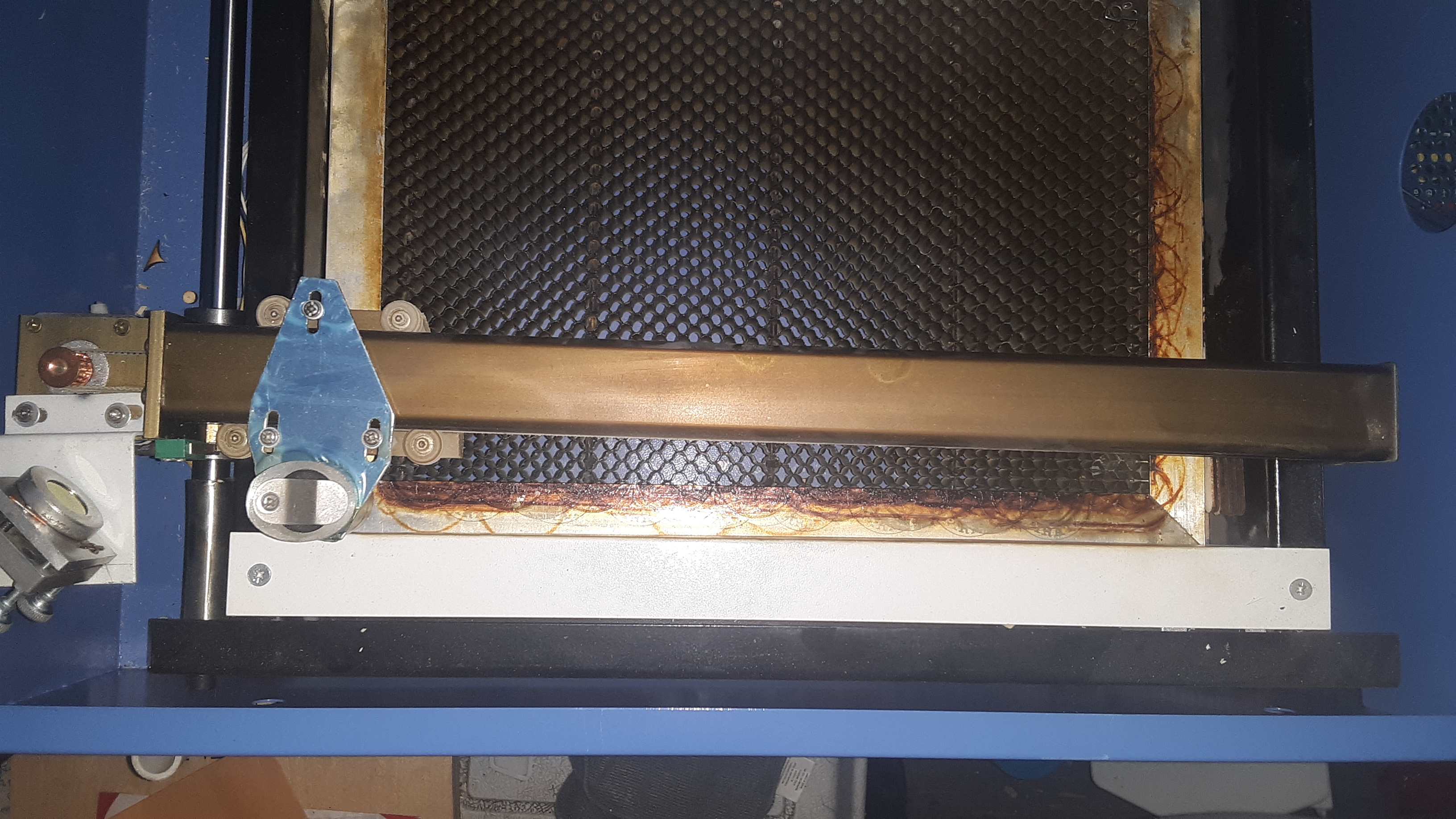
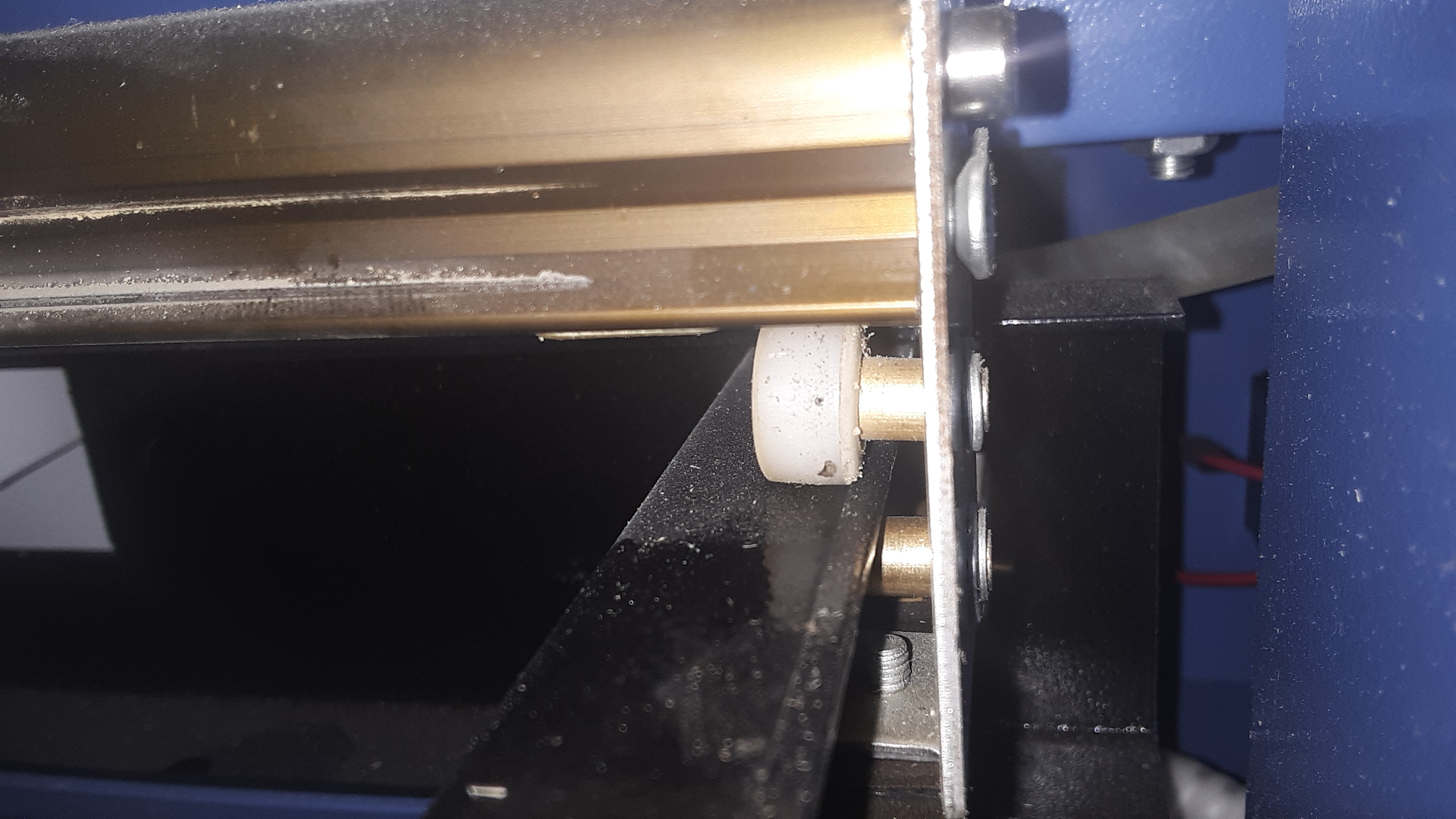
in the first pic you can see the gantry is quite skewed. The rail on the right that the rollers glide on: at the very back there is a tensioner. There should also be one on the left side also. There screws shown in pic 2 coming out of the end of the gantry are the same as you fill find at the end of those rails under the laser tube. Its a simple “C” style mechanism holding a roller for the belt to glide on, with one screw that tightens it by pushing against the rails. It might be easier to see this if you remove the entire gantry. I had to do that to adjust mine/comprehend how it works. Ideally the gantry rail should be square to the perpendicular rails in pic 1.
or you can remove the silver plate in pic one, loosen the coupling on the motor and adjust it till straight, then re-tighten.
Is it just me, or does the silver plate holding the mirror look skewed in comparison to the rail of the Y axis?
yea it looks a bit skewed but the mirror looks to be set properly, and thats the part that matters 
Ithe mirror alignment is close, but not quite aligned. Using the tape method, the positioning of the laser in the top right corner is about 1mm up and 1 mm to the right of the positioning in the top left corner. Not quite sure what I can do to better clean that up. The skew of the gantry was in the stepper positioning of each side. I’d guess it got knocked out of position during shipping. I was able to get the gantry straight without tightening the right belt, though it still needs tightening. That being said, I’d imagine the gantry will have to be removed or me to properly tighten that right belt.
as long as you can get the laser beam to hit the same spot in all 4 corners and it doesn’t clip the beam when exiting the nozzle then its good enough. It doesn’t always need to be perfectly centered in the opening on the laser head