many thanks for your explanation, but what kind of signal it is? can I use it to control co2 lps? I’m a little confused regarding TTL and PWM, as far as I understand PWM is a signal which controls frequency of pulses, while CO2 laser power being adjusted by the duration of the pulse if I’m not mistaken, or is it done by the lps itself, and we just need to send PWM signal to lps and it will convert it to pulse duration?
good questions. If you’d like to understand more about what “TTL and PWM” are then there are thousands of sites on the web explaining those.
As for how you controller works are you thinking you can just move a wire from one machine to the other and it’ll work? It might but you will have to look at what the base/carrier frequency requirements are for the CO2 and if your current controller is running GRBL or some other firmware you’ll have to see how to change that frequency. The CO2 LPS L input turns the laser output On when that signal is low(~0V). But often there is also an LPS H input which turns the laser On when the input signal is high(~3.3V).
If I did not have an Oscilloscope and I needed to tell what the diode laser controller was doing then I would disconnect a motor cable and the laser cable, draw a line in the direction of that axis in LightBurn, set the power to 100% and look at the laser control signal when you run the test line. If the voltage is 3.3V stead(ish) that you know the control line turns the laser on when the signal is High(3.3V). If the signal voltage is 0V then you know it’s active Low.
Just wondering, do you know you also have to setup 3 mirrors to bounce the INVISIBLE CO2 laser beam around and point it down through a lens to cut something besides just hacking an existing controller to control the LPS/Laser output? This is dangerous stuff and will blind you faster than you can blink and then turn the machine off with your remaining good eye…
1 Like
At least with a CO2 it effects the cornea, which can be replaced… Unlike a visible laser which effects the retina, that you cannot replace.
I’d suggest neither option.
I bought a pair of safety glasses at home depot and give them to visitors that want to watch the machine in action. Anything made from polycarbonate, like my glasses will block an IR emf emission.
PWM is Pulse Width Modulation, here is a link to the wiki, what you need to know about it is in the Duty Cycle section.
![]()
yes guys, I’m well aware of how to set up mirrors and also about precautionary measures, this is what I have studied at first, I also have more-less good mechanical engineering knowledge, just little weak on electronics part, but thanks for pointing out everything, I can not make a test just yet since the co2 lps not arrived yet, so just getting myself ready with your good help
quote
set the power to 100% and look at the laser control signal when you run the test line. If the voltage is 5V stead(ish) that you know the control line turns the laser on when the signal is High(5V). If the signal voltage is 0V then you know it’s active Low.
unquote
but my voltage on the control board is 3.3v at 100% power it does not go to 5v… also if the laser power set to 100% at Lightburn and the voltage shows 5v doesn’t it mean that the laser fires actually at 0v with minimum power and reaches 100% power at 5v ?
I’m sorry, I made a mistake mentioning 5V for the “high” value. just change that to 3.3v and it should all apply.
1 Like
Your pwm is on or off, so 0 is off and 3.3V is on… Post 25 is a link to how pwm works.
The lps expects a ttl level signal… A ttl signal is 0 to 5V, not 0 to 3.3V like on your controller.
However, usually anything over about 50% of the ‘on’ value should work.
The actual TTL specifications states:
Standard TTL circuits operate with a 5-volt power supply. A TTL input signal is defined as “low” when between 0 V and 0.8 V with respect to the ground terminal, and “high” when between 2 V and VCC (5 V) and if a voltage signal ranging between 0.8 V and 2.0 V is sent into the input of a TTL gate, there is no certain response from the gate and therefore it is considered “uncertain” (precise logic levels vary slightly between sub-types and by temperature).
Meaning that the 3.3V high should cause an ‘on’ state for an lps input that expects a high signal to be active.
If you want to use a control to the lps that is active low (such as L), the lps is probably pulling that input high to 5V, this would exceed your controllers tolerance.
![]()
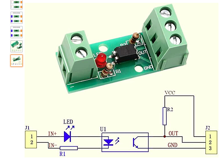
Given the info above I would give this module a try.
https://amzn.to/3ReQOa9
The intention is to convert the 0-3.3V swing to a 5-0V swing.
This would drive the L signal on the LPS. The LPS L input is expecting a ground (on) or 5v (off).
Since the L input is an opto coupler it needs to be as close to ground as possible to provide a solid “On” condition. Shifts above ground may cause the LPS to operate unpredictably. This is why I do not reccomend TTL levels.
Note: the opto isolation board has a LED and resistor in the input circuit.
Not knowing what the controllers PWM output looks like (sink/source) I would:
- Try the module with no changes.
- If that does not produce the proper output then remove the resistor and replace with a 100 ohm resistor.
- If that does not produce the proper output then additionally remove the LED.
Test setup:
Connect the PWM signal:
- J1-1: PWM
- J1-2: Ground
Connect the output:
- J2-1: 5VDC
- J2-2: DC meter.
- J2-3: Ground
The meter output at J2 should be the same as J1 but shifting from 5VDC to 0VDC.
If the LED is still installed it should be on and or flikering during the test.
Data sheet:
https://www.mouser.com/datasheet/2/143/EVER_S_A0008471837_1-2548735.pdf
con la scheda mks dlc 32 puoi collegare il laser L su spindle meno (pwm), oppure collegarlo su S a IN e G ttl a L
very useful information, thanks for everyone
Having hard times finding the same isolation board locally, could you please check which one I can try instead of the one you mentioned:
I need a location or zip code [germany?] so that amazon search will not try and find things that can ship to US.
please use this one 10115, Germany, please check the one which will be shipped by Amazon, there are a lot of chinese sellers, it will take ages to arrive from China, thanks
Looks like this is the same module able to send to Berlin?
hi, I was finally able to test the setup you recommended, at the output I read 5v at 0% laser power, which drops to 3v at 100% laser power, I didn’t remove resistor or diode, should I try to remove them? or maybe to try to fire up laser with no changes? how should I connect this opto board to the lps? thanks!
Go through the above 2 steps in sequence.
After each step report on the voltage levels as you have done previously before you go on to the next step.
hi, I have replaced the resistors and led with the wire, I was able to get constant 5v on the output ports, I have connected J2 to H port and ground to G, there was nothing connected on IN port, only WP to G, unfortunately there was no any output from the laser, after that I have removed opto coupler and connected control board straight to lps - PWM to IN, ground to G, pulled L to G, WP to G, my PWM has 0-3.3v range, and I was able to get laser output to a maximum of 21 mA out of 26 mA lamp specs maximum, I have played a little with the power settings in Ligtburn, and it looked like the laser responded correctly, the minimum mA at which the lamp produced the proper beam was 7-8mA, I didn’t try to use it in normal operation since it is just in a testing stand. Could it be the solution to control the laser like this? Is it correct in general? If yes what is the simplest way to dynamically increase the current from 3.3v to 5v, so when I set it at 10% of power it will produce 0.5v instead of 0.33v? thanks
I am not sure what this means.
If you change the PWM on the input to the optocoupler it does not vary the output on the optocoupler?
The resistor is not supposed to be replaced with a wire but a 100 ohms resistor
You probably have fried the Optocupler.
Previous instructions:
- Try the module with no changes.
- If that does not produce the proper output then remove the resistor and replace with a 100 ohm resistor.
- If that does not produce the proper output then additionally remove the LED.
[/quote]
.
I did like you said, replaced with 100ohms, opto coupler with no changes provided 5v at 0% power and 3v at 100% power, but after I replaced the resistors it was 5v constant, same after replacing led, there is a chance that I did something wrong, but actually it wasn’t something complicated so it looks like I followed your instructions exactly as it written… Should I order another one and try again ? There are 2 resistors, should I replace them one by one or same time? What are the voltages we are looking actually at the output? 0-5v ?
I will send you a restart set of instructions later today in visual form.
I should have been clear about which resistor to change. It is only R1 that should be changed.
Wouldn’t hurt to go ahead and order another one or two.
Below are more detailed drawings that I hope will help.
First off:
In answer to your question:
This may work but it’s possible you won’t get full power from the LPS.
You can tell if you are getting full power from the LPS by:
- Connecting IN to 5V
- Push the test button on the LPS and note the current (Caution this should fire the laser)
This will represent the max current you setup will produce
I still recommend the setup we started with. You get a few benefits:
- Proper level shifting
- Additional Isolation between the controller and the LPS since we do not know what the controller’s output circuit is.
- Local control (pot) of the overriding laser power
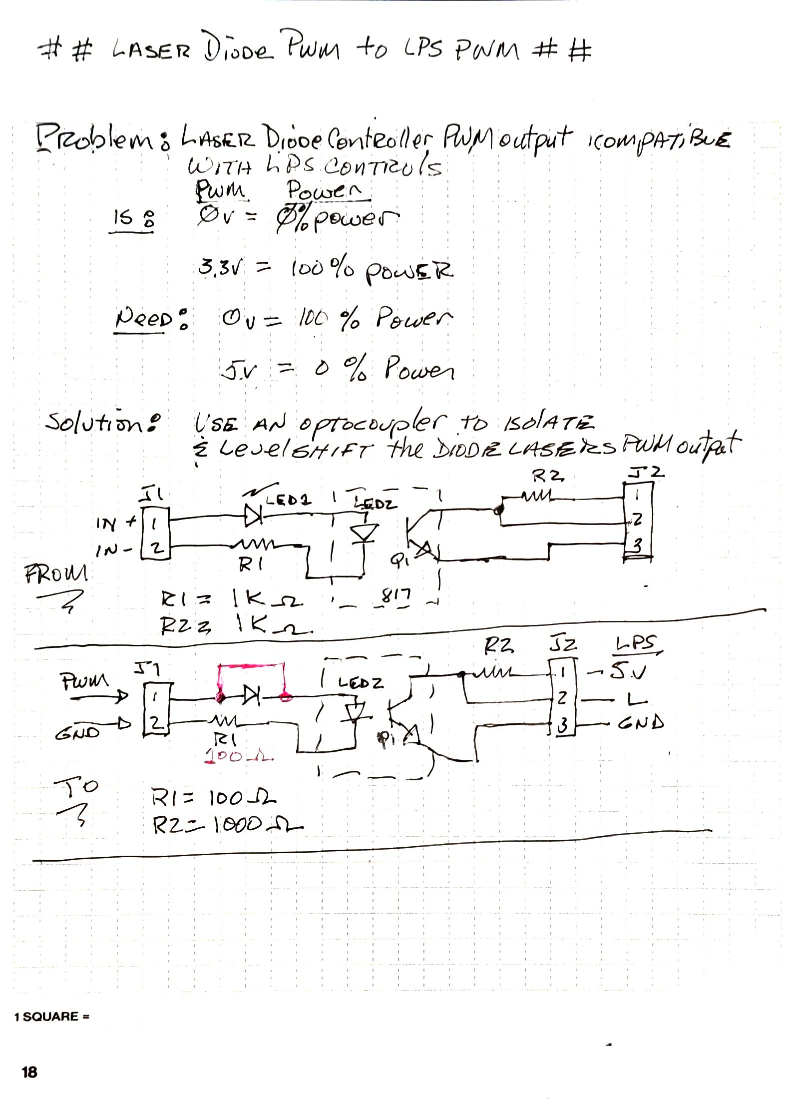
This drawing shows the before (as shipped) and after configuration of the optoisolator for this setup.
- R1 is changed to 100 ohms
- Led1 is shorted out. You also can remove and replace with a wire.
- No changes to R2
Note: this is setup to drive the LPS L pin.
This drawing explains how to test the setup before connecting it to the LPS including a description of how it is supposed to work. If the setup does not behave like this then something is wrong and we need to discuss it again.
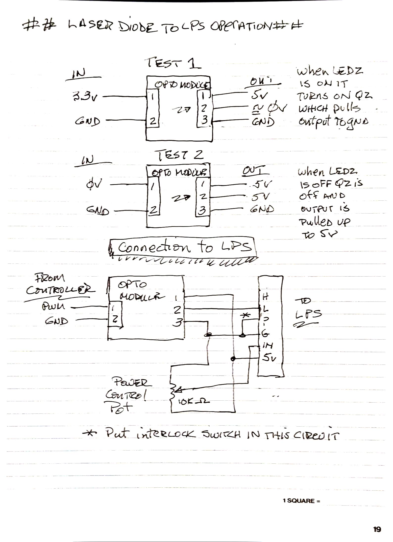
That drawing also shows how to connect the isolator to the LPS.
Note as the drawing shows you also need:
- The IN to have a local pot to control the power. Alternately you can just connect it to 5V. It cannot be just left open
- The P (or wp ) must be grounded