Hi, I have a Diode laser and would like to upgrade it to CO2 without changing the control board and frame since it is amazing equipment. The control board has a PWM signal which I need to convert to 5v TTL in order to be able to control CO2 laser power supply. The PWM control of my diode laser works like this: 0% power - 12.17v /// 50% power - 10.52v /// 100% power - 8.87v. So it is inverted PWM control in a limit of 3.3v total. Does anyone have an idea if there is a chance to convert this to 5v TTL, and to point me out the right direction. I have attached pictures of my control board and CO2 power supply. Many thanks!
You do not need (not want) TTL to control the laser power supply.
You just need to pull the L signal to the ground. You could do that with any kind of electronic switch like a transistor, MOSFET or even an opto isolator (ideal).
thanks for your reply, I have some mechanical engineering skill but very weak on electronics, could you please explain what does it mean to pull L to ground, and how to do this
1 Like
Sure I will provide some more detail in the next few days unless someone on here beat me to it. ![]()
are you sure it is not 5V TTL to the laser module driver board and it’s the driver board which converts that to varing 12V to the laser module?
I’m pretty sure the Ortur diode lasers have 3 wires to the laser module, one 12V, one 5V TTL and one Ground.
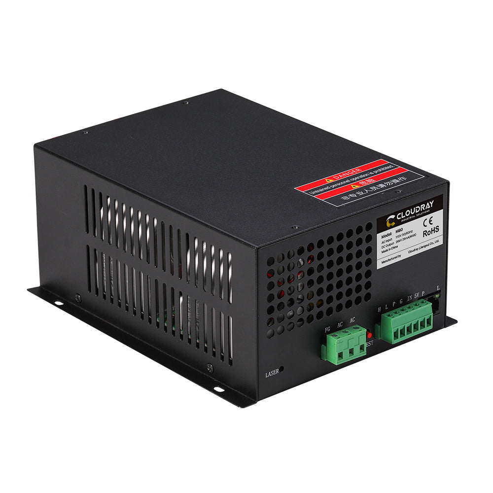
The lps in the photo has an H input for an inverted Laser Enable signal… that’s used like the K40 with a dc supply to the IN of the lps.
I find it real odd that they voltages are what you describe… I have a NEJE 40603 laser module and it works as described by @dougl.
I haven’t seen any of these pwm being inverted, seems odd. I have 3 ss lasers and they all use a positive ttl level pwm signal.
Not to mention an inverted 30% pwm is a 70% pwm…
![]()
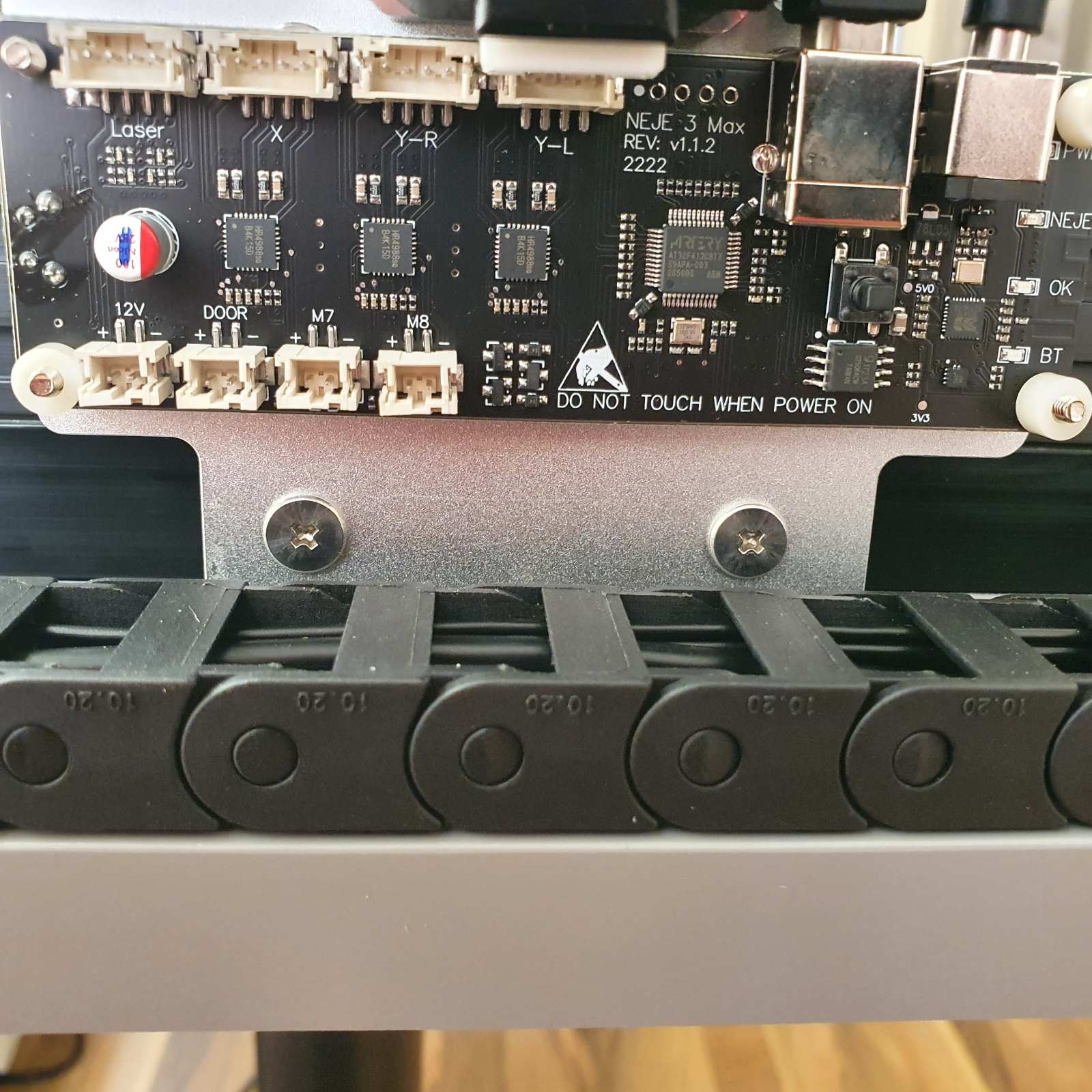
I also find it very odd, but that is what I was able to measure… I have Neje 3 Max + E40 laser module, laser module has 4 pins connection with built-in temp sensor and fan. There is 1 positive and 3 negative cables coming from the main control board to the laser module. By playing with the laser power settings in Lightburn I was able to measure voltage changes only on one pair of cables, the other two shows 12v constant. And it is as I described before: 0% power - 12.17v /// 50% power - 10.52v /// 100% power - 8.87v. If I slowly increase laser power, it slowly drops from 12.17v to 8.87v. And I have absolutely no idea hot to make it work with the CO2 lps…
How and with what are you making these measurements?
1 Like
With a simple multimeter connected to the output pins of the control board
@horhe it’s pretty common to switch the connection to ground on and off (a “low side” switch, so you will probably be able to just use that connection.
But when you say “1 positive and 3 negative” — positive and negative are relative to each other so you’ll need to be more explicit about exactly what you are touching to make the measurements you are referring to.
1pin+2pin=12v, 1pin+3pin=12v, 1pin+4pin=12v
2pin+3pin=0, 2pin+4pin=0
3pin+4pin=0
1pin+3pin= reacts to laser power adjustment on the software, others not
Find the ground lead or area and use that as ground. You should read 0 to 5 volts on the ttl/pwm input and 12V on the laser…
You can test the ttl/pwm… 50% pwm should read 50% of the output max, which is a 5V ttl level. The neje will tolerate up to 12V on the pwm, but it only switches within ttl limits.
The temperature output, I was hoping to use but following their suggestion … I got this…
The NEJE documentation for mine states
NOTE:Temperature interface can be disconnected,NEJE provides text instructions for temperature acquisition on the wiki.
the NEJE wiki instructions from the wiki
Temperature: do not connect, please ignore.
Kind of hit a dead end… with temperature …
![]()
So it sounds like pin 1 is 12V supply, and pin 3 is a low-side switch to ground.
@donkjr is there any reason not to just connect L to pin 3 here?
thanks Jack, but you are overestimating my understanding of the subject ![]() How to find the ground lead or area? Where I should read 0-5 on the input? What I understand for now is that I can manually control the “basic” laser power by potentiometer between 5v,IN,G of the lps inputs. So if for example I will set it manually to 50%, and set the laser power in software to 50% as well, it will result in 25% of the actual laser power. So now we need to find the way to programmatically control the lps from my main board. The one way to do it is to send PWM signal to the L input of lps, and also ground to G input of lps. The PWM signal should be from 0v to 5v where 0v is 0% power, and 5v is 100% power, is this correct?
How to find the ground lead or area? Where I should read 0-5 on the input? What I understand for now is that I can manually control the “basic” laser power by potentiometer between 5v,IN,G of the lps inputs. So if for example I will set it manually to 50%, and set the laser power in software to 50% as well, it will result in 25% of the actual laser power. So now we need to find the way to programmatically control the lps from my main board. The one way to do it is to send PWM signal to the L input of lps, and also ground to G input of lps. The PWM signal should be from 0v to 5v where 0v is 0% power, and 5v is 100% power, is this correct?
If it’s got a dc control voltage on the IN, then the H terminal (active high) is correct… If in fact, it is inverted (which I doubt) you can use the inverted L input (active low) for laser enable.
@horhe The ground is usually the usb shield, but we know on your machine that there is a ground going to the laser module… Use that one
Generally what you have stated is in line …
I set mine up a bit differently, my lps has an internal current control so I can set the lps current limit there, then all percentages are correct in the software. 50% power will allow 50% current (power)… Mine won’t lase below around 9%, but I don’t attempt to run it that low anyway.
![]()
so i guess just connecting it straight will not work since the PWM signal on my board inverted and higher than 5v (12.17v - 8.87v), so do we need some extra hardware programmed to output 0v while there is input to it of 12.17v and output 5v while there is input of 8,87v?
it looks like this is the example of the hardware required, but the price + shipping to my country + VAT would be around 250-300 usd which is crazy for the cheap chinese 1 dollar stuff…
that looks like an STM32 clone and I see 4 empty .1" on center header pin sockets at the top of the board near the USB connector. That is likely the ST-Link programming connector and on that will be 3.3V and Ground along with a data and a clock line. Use your DMM in Resistance setting and measure from the case of the USB connector to each of the 4 empty pin holes(WITH POWER OFF and USB DISCONNECTED). You will find one of those gives you ~0 ohms resistance.
Put you DMM in voltage scale(0-20V), power on the controller and with the black/negative DMM test lead on the pin hole you found with 0 ohms you can then put the red DMM test lead on each of the other 3 and you should find a steady 3.3V on one of them. Under the board it is likely marked Vcc and this validates you have found a good ground point for the board.
Now move the red DMM test lead over to the 4 pin Laser connector and make your measurements.
You are measuring the voltages on the Laser connector “relative” to Ground.
1 Like
I think you (or me) misunderstand. These modules don’t use a ttl signal like you describe. In fact that is not a ttl signal which is basically from 0 to 5V.
I think we are betting that you are measuring from 12V to PWM or something that is making your measurements off of what they should be.
I have virtually the same module that is supposedly interchangeable, manufactured by NEJE, it and others do not use the voltages you described …
I think we can only assume you’re not properly measuring it…
Follow @dougl advice to find a proper ground …
Good luck…
![]()
can’t wait to share with you my findings ![]() you were absolutely right, so firstly I found the pin with 0 resistance, it was the first one, 3.3v was the first + fourth, than I measured the laser socket pins and the third one was 0v - 3.3v signal according to laser power (0v - 0%power, 1.65v - 50% power, 3.3v - 100% power), so what does it mean for us now? Is it enough to control the co2 lps or not yet? many thanks!
you were absolutely right, so firstly I found the pin with 0 resistance, it was the first one, 3.3v was the first + fourth, than I measured the laser socket pins and the third one was 0v - 3.3v signal according to laser power (0v - 0%power, 1.65v - 50% power, 3.3v - 100% power), so what does it mean for us now? Is it enough to control the co2 lps or not yet? many thanks!
1 Like
good to hear and remember, measuring voltage is a relative thing. Much like how we measure people’s height relative to the ground… Measuring voltages is almost always measured relative to the Ground potential(sometimes marked as Neg like on a car battery or even 0V) and usually with a black colored wire and black test lead. The red test lead is what you move around to measure the voltage potential ABOVE ground. A measurement of a Low TTL signal should be 0V but sometimes below 0.8V(TTL) or 0.3v(CMOS) are acceptable due to how electronic circuits trigger and switch states.
1 Like