Hello friends! Firstly - thanks for such awesome community, I have studied a lot from this forum! Currently, I’m in a process of building DIY CO2 laser on my Neje 3 max frame. In general the process looks to me more-less understandable, but there are some specific moments which I kindly ask you to help me to clarify, it is related to safely, hardware and electronics. I will start from the safety:
as far as I know any acrylic will block CO2 laser reflections, I also know that opaque orange acrylic will block blue diode laser, my question is - would transparent orange acrylic block blue diode laser reflections as well? Maybe someone with blue diode had experience on cutting transparent orange acrylic, does the laser just goes through or does it actually cut?
what would be the best and simplest way to implement interlock to enclosure?
how to handle the high voltage power supply in a correct way, should I isolate it with some rubber pads while mounting, or it will have no safety effect? Should I do additional grounding, or the one which has regular power cable with 3 pin plug is enough, and it is grounded by default?
So while Plexiglas 2422 doesn’t come with a certificate, it is our understanding that it has the same dye that is in the certified plastic. It is possible, of course, to buy plastic that is tested and certified for blocking 455nm laser light.
There’s a link in Why orange plastic for CO2 lasers? - #9 by mcdanlj to a post that goes into a lot more detail on acrylic transmittance. Apparently thickness really is important! I am not an expert here, I’m just a collector of links using them to make my own decisions for my own laser…
Note: Safety glasses are not a way to avoid nor do they replace interlocks.
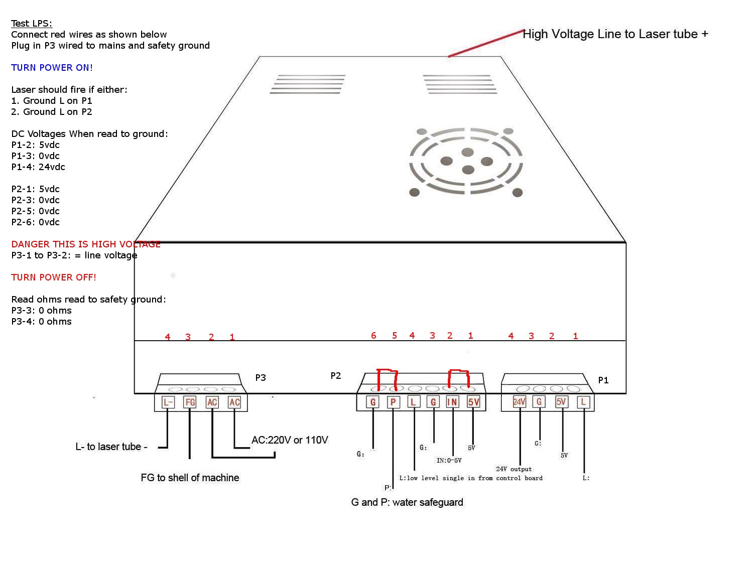
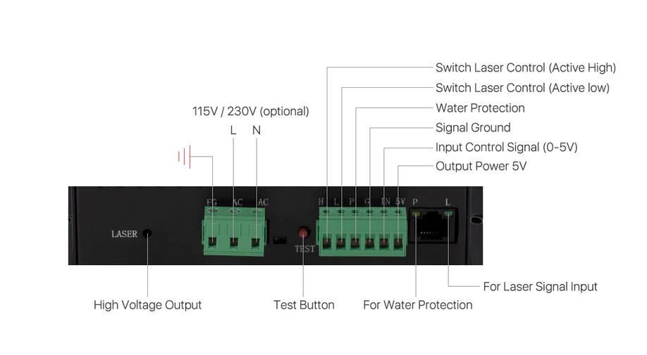
what would be the best and simplest way to implement interlock to the enclosure? Generally, add microswitches on all accessible areas and connect in serial to the WP pin on the LPS. The exact circuit will depend on what supply you are using.
Post a picture of the LPS you are using.**
how to handle the high voltage power supply in a correct way,
should I isolate it with some rubber pads while mounting, You definitely do not want any electronic enclosure floating from the ground. You want the LPS and the cathode of the tube tied electrically to the frame. The mounting screws and the FG pin usually provide adeuate connections. Depends on exact supply. or it will have no safety effect?
Should I do additional grounding, The frame and the FG pin on the mains connector should be enough. I use a stud in the frame and star pashers on the ring tounge.
or the one which has a regular power cable with 3 pin plug is enough, and it is grounded by default?
[/quote] It should be. Thoroughly check that the ground pins and cases on all electronic elements are electrically at ground. There are lots of posts on this forum about grounding design for minimal noise. Don's Laser Things: Search results for grounding
Other things to consider.
Keep control electronics wiring as far away from motors and the LPS as possible.
Use single point, not daisy-chained grounding designs.
Keep sensor and control wiring as short as possible
Use as large as practical ground wiring
In sure all metal and operator-accessible surfaces are at safety ground.
Great tips, Don! I do find it interesting that you recommend the cathode of the tube to be tied to the frame. Could you elaborate? Or do you mean it’s tied via the FG pin on the PSU?
I had issues getting some electrical shock when touching the frame of my laser sometimes, but I have since grounded the frame entirely to a bus bar which is tied to the AC ground. I haven’t come across the issue again, but wondering if I should tie the FG pin and now the Cathode? to the frame? Thanks in Advance.
Yes.
It is always best to connect a power supply’s load ground directly back to the supply’s ground.
It would have been better if I had said: You want the LPS and the cathode of the tube tied electrically to the frame but physically connect it directly back to the LPS [L-] pin. Then ensure the LPS is grounded to the frame via the FG pin.
Thank you, sorry, maybe I should have been a little more clear as well, I don’t have a PSU like the k40, my cathode from the tube returns to a wire that is internally connected to the power supply, so I don’t have an L- Pin accessible on the outside of the LPS, so I may have been confused thinking I needed to connect Cathode to that wire AND a frame ground.
On my OMTech, the lps is grounded to the frame, from the factory. I tested the mA meter with a connection to the frame. When is standardized the wiring, I did run it to ground of the lps.
On my lps, the only L input is for laser enable.
Is there something different about the -L input of the K40 style lps?
It just ensures that the current from the tube returns directly to the supply.
Some LPS have a separate ground wire and no -L.
I haven’t seen a supply without some kind of a cathode return.
I show it going to the -L side of the HVT secondary. However, when I measure it to FG it is connected. As I remember the -L and FG are connected together.
Yes and no. The primary side of the HVT is isolated from ground [part of what makes this supply challenging to work on]. The secondary side of the HVT is connected to -L, FG. On the supply I measured, I can see it connected at the connector.
I have seen them with no cathode ground and with a pigtail out the back.
I have never seen one. These manuf. are not willing to part with one. I do not have one of those supplies so I did not reverse eng. since the controls are about the same.
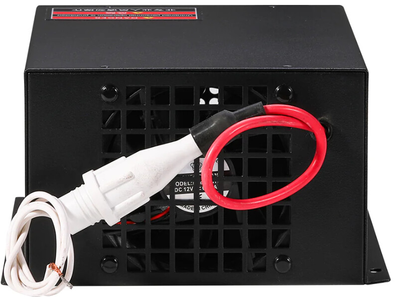
This is the rear of the power supply, the white is connected to the return line from the tube. So from my understanding, if my FG pin is indeed grounded to the frame and AC input ground, then I should be good? I don’t need to ground this white white for the return to the frame? I can check the wire with an ohmmeter (after a good period of no use of the tube, of course) and if it has continuity with the frame, is what I’m understanding from your later post on this thread, right?
Late to the party and I see the OPs questions are getting good answers, but heres mine:
Why convert to CO2? I recently bought a 20W optical power LaserTree Diode head and it kicks my upgraded K40s ass so hard its a joke. One pass cuts on 3mm plywood causes a LOT of charring so narrow parts get burnt with the K40. With the LaserTree it cuts 6mm at 3mm/sec and 80% power, nice clean, zero charring on thin narrow. Same with cutting Garolite(fiberglass), the K40 struggles, the LT does it easily.
I’ve had the K40 for over 6 years and have upgrade the mirrors/lens/head and controller, its a contant struggle to get really consistant cuts across the entire bed, problem eliminated with a Diode. No water cooling, no high voltage, no impact/shock sensitivity. FWIW, my LT head is on a large format DIY setup, K40 is not designed to accomodate a Diode easily.
I had 3 diode lasers before I bought my second hand K40. Although the diode lasers were not top quality, they could not really cut anything other than 2mm birch ply, each lasted around 6 months to a year at the most and I had to build a cabinet and extraction fan to extract smoke. Cutting for me was a key objective and so the K40 seemed the most cost-effective solution with its cabinet and extraction in place which was essential. Although I did have some problems early on and had to buy a new tube and PSU, these cost just over £200 alongside the £300 initial purchase price. I also then had problems with cooling and resolved this with a home-made chiller system meaning I can have long cutting sessions within tube parameters then a better air assist solution, now sorted and finally difficulty in mirror re-alignment which is poor on the base product which I resolved recently by upgrading to the Cloudray Head Set including mirror holders, mirrors and lens which now gives me all the alignment adjustments I need. This has been a highly successful upgrade so along with serviceability changes and processes I use for its semi-professional use, my K40 is simply humming, cutting 3mm ply and MDF consistently in one pass well within maximum tube limits and acrylic in 2, cutting jigsaws and 3D models with superb accuracy and I have not noted any of the issues in quality of cut described. I also had intended to upgrade the controller board in order to support Lightburn but I find that I am totally satisfied using K40 Whisperer and designing in Inkscape for cutting projects. Although I exclusively use 3mm ply and MDF for cutting projects and 2mm MDF for jigsaws at 10mm/s 15mA, I did try 6mm MDF and it cut through in a single pass at 6mm/s. I noted the Laser Tree 20W costs around £240 and presumably its cutting performance will decline in due course so on balance I am very happy with my K40 investment although I admit that I would like a larger format than 300x200mm.