Hi everybody, I’m a noob both here and with electronics in general. I’m trying to get a DC motor working with my ESP32, using a motor driver board TB6612FNG. It doesn’t do anything after I upload the sketch.
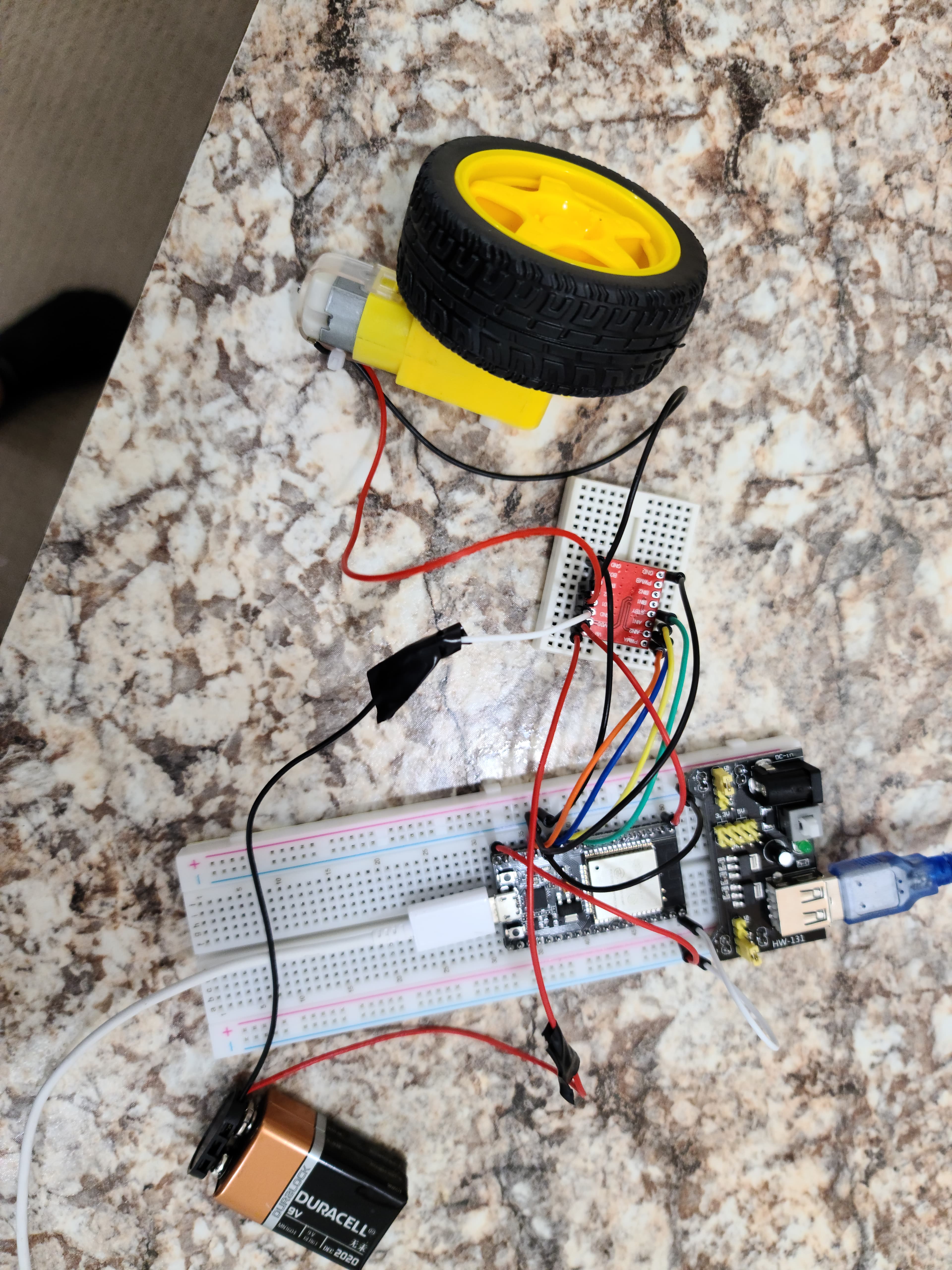
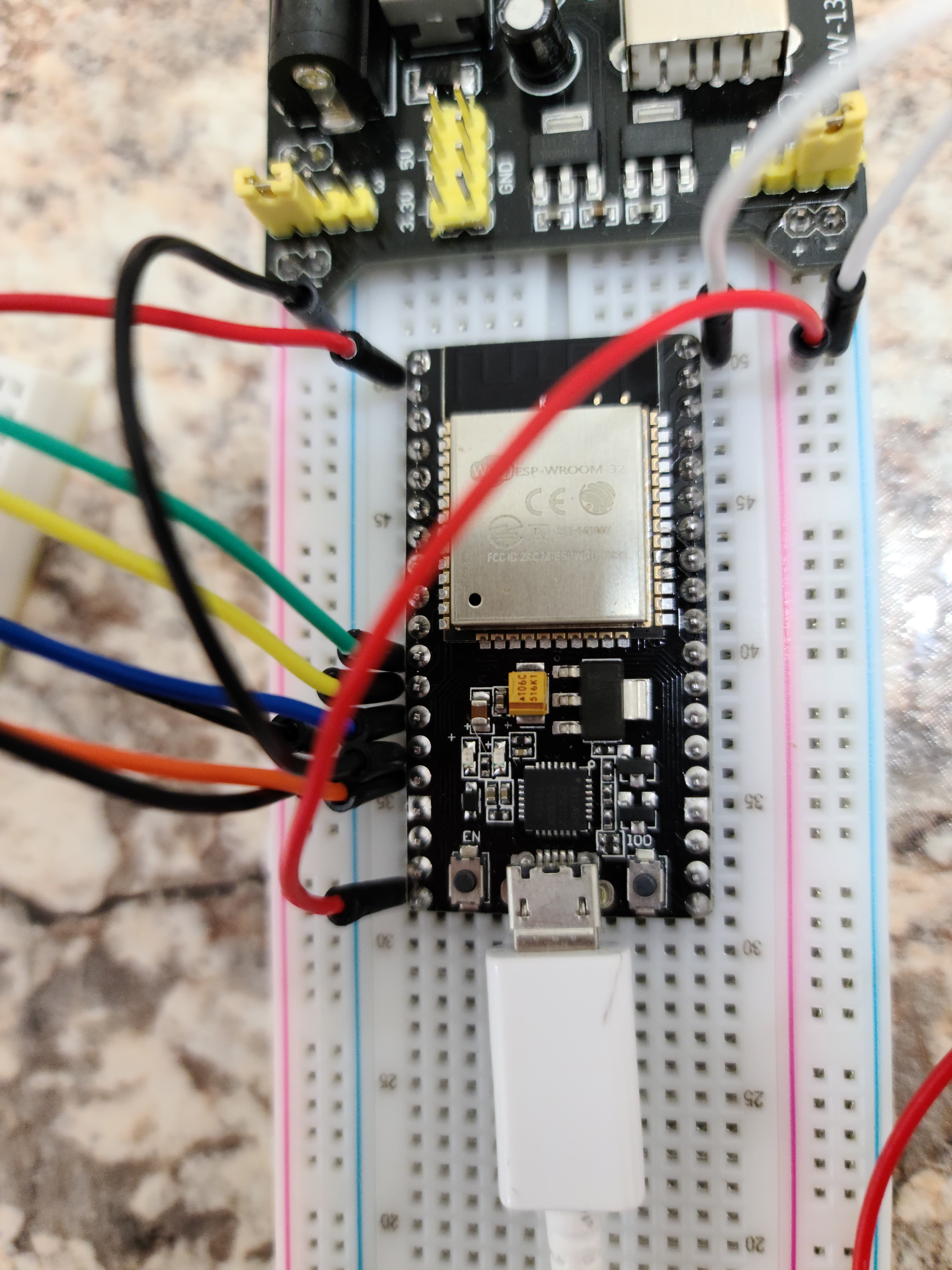
Here’s how I hooked it up:
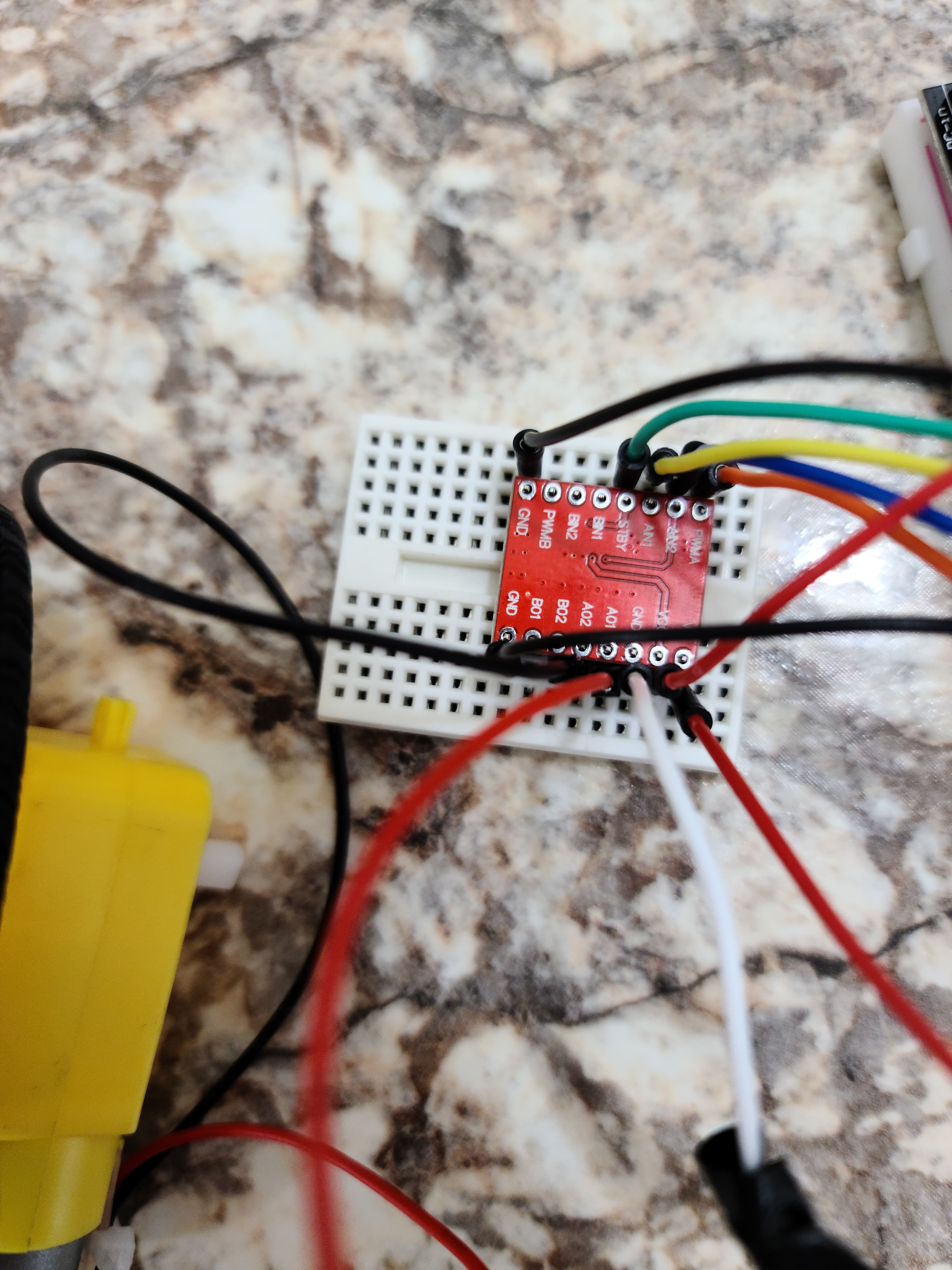
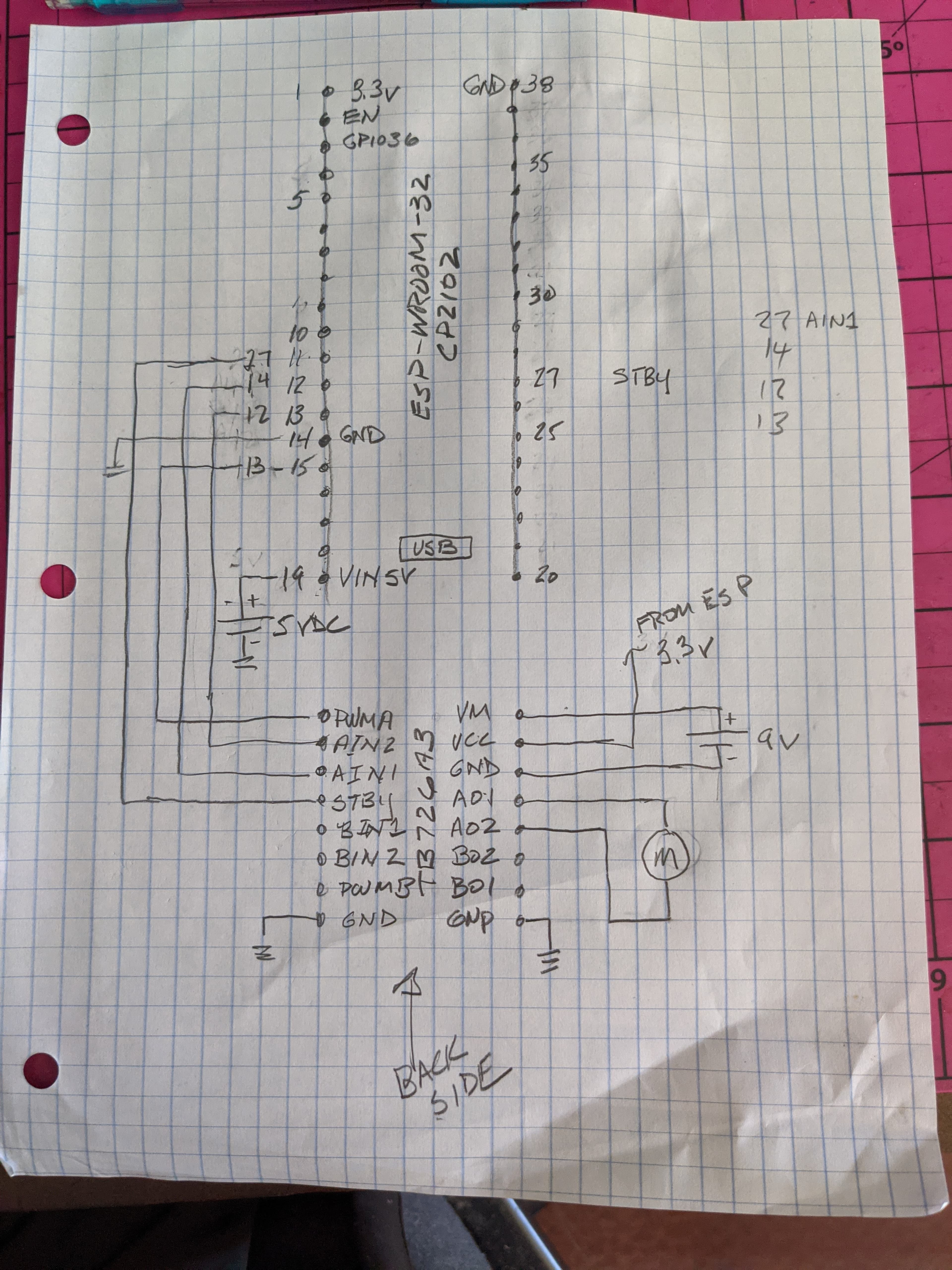
VM → 9v battery positive
VCC → 3.3v output pin 1 from ESP32
GND → 9v battery negative
A01, A02 → DC motor
STBY → GPIO27 (11)
AIN1 → GPIO14 (12)
AIN2 → GPIO12 (13)
PWMA → GPIO13 (15)
GND 1, GND 2 → GND (14)
I copy/pasted this sketch without modifying it:
I was able to measure 3.3 volts on the TB6612 VCC, and 8.9v from the VM. But the motor doesn’t move (if I hook up the battery directly to the motor is does). The Serial Monitor prints the Loop message so I know the sketch is running on the ESP32 properly.
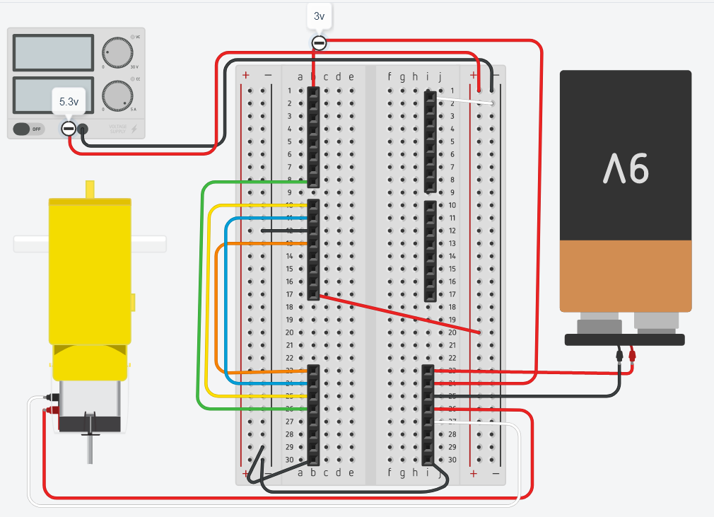
Hi Don, thanks for replying. Happy Friday! Sorry for taking so long. I looked for a good breadboard layout solution and found that Tinkercad has one, so I whipped up a wiring diagram.
Firstly, to answer your questions:
Are you using a motor driver board or directly wiring to the TB6612?
The TB6612 is the motor driver board and I’m wiring up the ESP32 directly to it.
The four sets of 8-pin headers represent the 32-pin ESP32. The two lower sets represent the TB6612FNG board. I couldn’t figure out how to overlay the pics in Tinkercad so left it as-is.
The TB6612FNG pin layout in the wiring diagram is as follows:
Left Side:
1 - PWMA
2 - AIN2
3 - AIN1
4 - STBY
8 - GND
Right Side:
9 - VM
10 - VCC
11 - AO1
12 - A02
16 - GND
Schematic?
I included a wiring diagram pic
I assume the code compiled with no errors or warnings?
No errors or warnings.
Hi Don, thanks for the reply and for your time on this. When I get some time over this weekend I’ll try out your suggestions. I had heard from somewhere that STBY needed to be HIGH in order for it to work, and the code I use asks for the STBY pin in the class constructor. But it won’t hurt to try disconnecting it.
I also saw someone in a different forum talk about it working after they soldered the header pins, which I haven’t done yet. I just placed the headers in the breadboard and placed the TB6612 on top without soldering. Maybe soldering will do the trick.
Your schematic is exactly how I have it; I’m glad to see my diagram was readable. lol
I did try the code from SparkFun that you suggested and since I couldn’t get it to work decided to use this other one since it was a lot simpler. Needless to say, it didn’t work either.
Thanks for your help and I hope you have a great weekend!
Hi Don, sorry for the long delay. I accidentally fried my ESP32; I’m not a very good solderer. lol So I had to wait for the new one to arrive from Amazon. It worked! (after I cleaned up my bad soldering job )
Thanks again for your time on this; it was greatly appreciated!