Uploading: 20210627_074254.jpg…
Goodmorning everyone
I bought the AWC7813 trocen controller for my k40 but I’m not sure how to connect all the wires especially between the MYJG40W controller and power supply or I followed the diagram supplied with the controller but I don’t understand all the connections some of you know or use this controller I ask for help to you
if you have a diagram of how to connect all the wires
Sorry for my bad english i translated with google
thank you
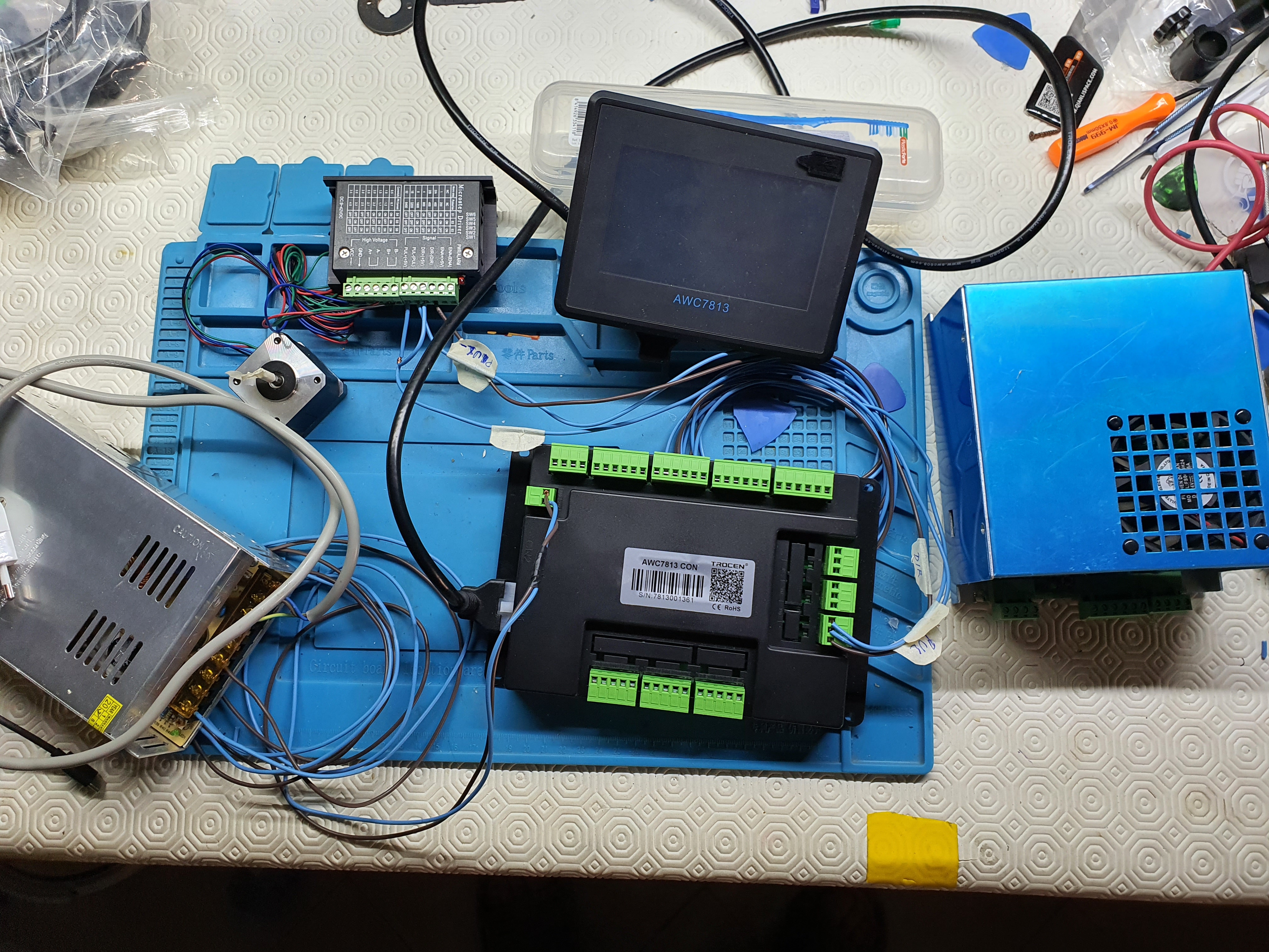
Questo è come ho collegato i fili per provare se funzionava il controller l’alimentatore MYJG40W e uno vecchio non funzionante messo nella foto per farvi capire quale alimentatore possiedo
Think about what you have there… and in most laser cutters
1 - a motion system which usually consists of 2 stepper motors and 2 home/end-stop switches
2 - a laser to turn on/off and maybe adjust power level
I would hope there’s documentation on what connects to the stepper motors and what connects to the end stops.
Once you get that going so that you can control the machine with the attached display and then with the software you expect to use with it the next step is turning the laser on/off and power control. The stock K40 laser power supply(LPS) has 2 means of control, one is the max power level set by a voltage on the “IN” connection. It is usually a connector which included 5V and Ground around the IN signal. This is because a variable resistor(POT) if often used to set that max voltage/power by putting 5V/Grn across the POT and connecting the wiper of the pot to the IN signal. For dynamic laser control, PWM signal( often at a 5KHz frequency) is sent to the “L” signal on the other connector of the LPS. It will usually be with 24V/GND/5V/L labels.
Since you have your own 24VDC power supply for the controller and stepper motors you only need to connect a Ground wire between the 2 power supplies which is a common ground so that the L signal can have a circuit path with the controller.
1 Like
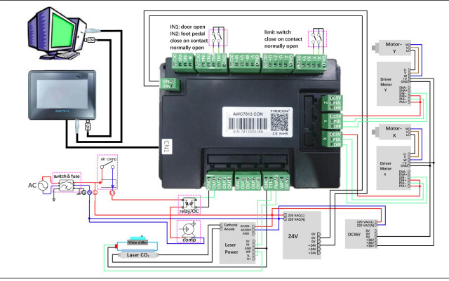
See if this helps"
2 Likes
Grazie per il tuo aiuto pensavo fosse molto più facile e che avrei trovato qualche guida passo passo
Lo schema che hai postato è quello che o trovato nella confezione del controller ma ci capisco poco
Grazie comunque
You will benefit greatly by having a small understanding of how this works instead of just connect things as a Step-by-Step would provide. When you understand even a little bit, things like what Don just posted become your Step-by-Step along with thousands of other things. Learn from the challenge and have fun!
1 Like
Si hai pienamente ragione capisco bene cosa intendi sono un autodidatta ma purtroppo mi manca il tempo il mio lavoro mi porta via troppo tempo
Grazie farò come dici tu
[quote=“Salva, post:5, topic:83437, full:true”]Grazie per il tuo aiuto pensavo fosse molto più facile e che avrei trovato qualche guida passo passo
[/quote]
Thanks for your help I thought it was much easier and I would find some step by step guides
[quote=“Salva, post:6, topic:83437, full:true”]
Lo schema che hai postato è quello che o trovato nella confezione del controller ma ci capisco poco
Grazie comunque
[/quote]
The schematic you posted is the one you found in the controller box but I understand little about it
Thanks anyway
Si hai pienamente ragione capisco bene cosa intendi sono un autodidatta ma purtroppo mi manca il tempo il mio lavoro mi porta via troppo tempo
Grazie farò come dici tu
Yes, you are absolutely right I understand what you mean I am self-taught but unfortunately, I lack the time my work takes me too much time
Thanks, I will do as you say
What form could we put the information in so that it would be easier for you?
In quale forma potremmo inserire le informazioni in modo che sia più facile per te?
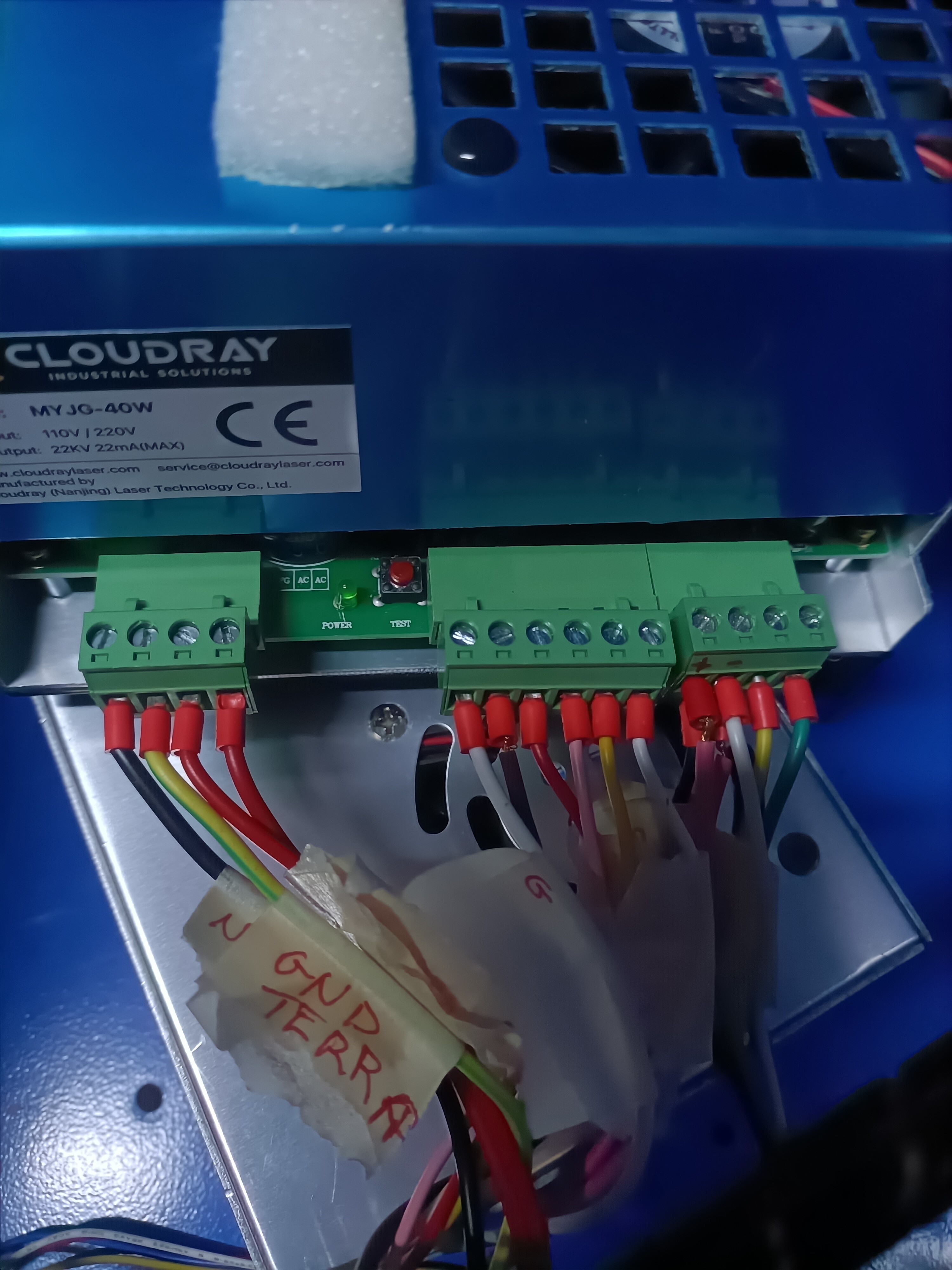
Please post a picture of your LPS showing the green connectors
Hi @Salva! This forum is now (and for the foreseeable future) available entirely for free and without any advertisement. This means that there is no source of funds to pay for automatic machine translation. The common language on this forum is English, even though it is not the first language for many forum participants.
Please feel free to use machine translation like Google translate, Bing translate, or DeepL translator in order to post here in English, as well as to read responses.
hello in my spare time I was able to connect the motors now I wanted to understand how to connect the limit switches in the controller
then I do not understand what are the ones that I have marked in green
thanks for your help
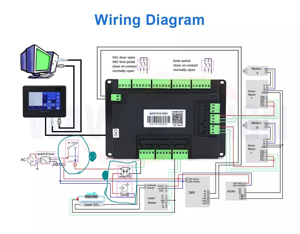
Those are for Air Assist. Please read all of the FAQ at http://k40laser.se and the FAQ at the top of this page. You should know what air assist is and how it is implemented and therefore would have known that “air comp” means “air compressor”, etc.
That circuit is so that the controller can turn on/off the air assist. Many K40 users do not have the controller doing this and have a mechanical switch somewhere else.
1 Like
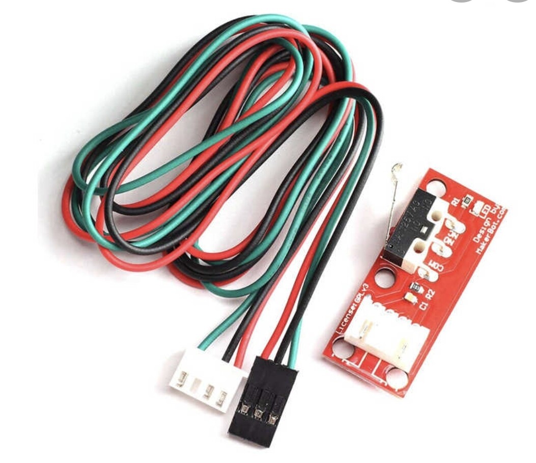
thank you sorry if I take advantage of your availability and courtesy you can help me understand how to mount the limit switches I attach an image of those I have at home
[image]
I do not have that controller and you will need more than a picture of the controller to connect your end stops.
Did you see the words “limit switch” at the top of that picture you posted? Somewhere along that row of connections on the top of the controller(in the picture) is where you connect your end stops/limit switches. FYI, the end stops limit the travel of the motors or are at the end of travel hence the names “end stops” and “limit switches”.
Grazie dougl
Alla fine ho collegato tutto e funziona avevo un po di perplessità per paura di sbagliare e fare danni comunque ancora grazie per l’incoraggiamento tutto sommato avevi ragione ho imparato qualcosa che prima ignoravo
Ciao
Thanks Dougl
In the end I connected everything and it works I had a bit of perplexity for fear of making mistakes and doing damage anyway Thanks again for the encouragement all in all you were right I learned something that before I ignored
1 Like
sorry I wrote again in Italian
I also do not have this controller but I know many K40 users do.
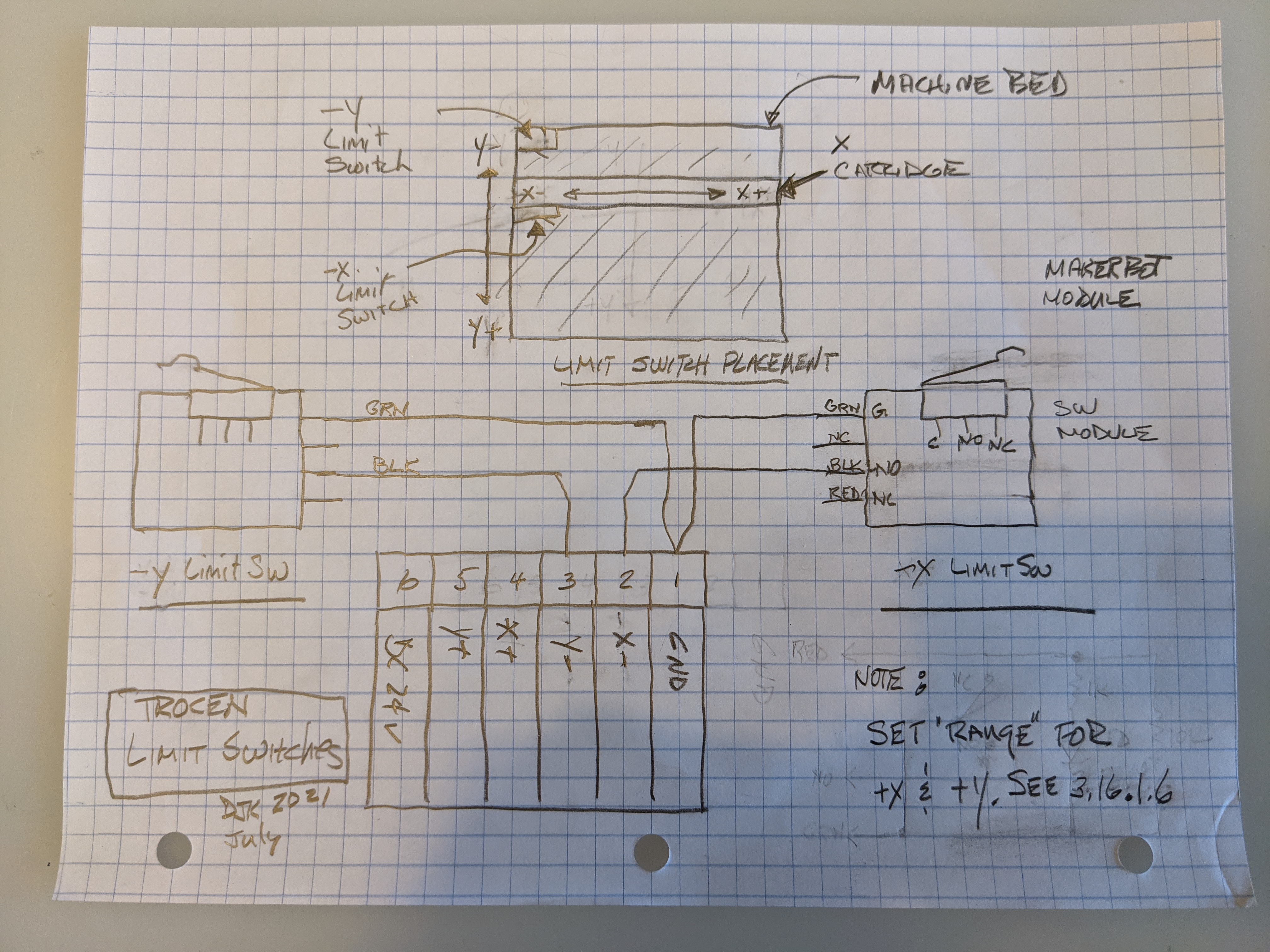
This diagram may help?
I guessed the best I could from the limit switch instructions in the trocan manual cited above.
I also assumed that the limit switch modules are wired like the standard Makerbot ones.
After you install the switches and wire them to the controller I suggest you check the -x and -y on the connector to verify that when they are activated they provide a ground (pin-1) to pin 2 & 3.
You have to set your +x & +y max in the controller settings. See 3.16.1.6 in the manual.
EDIT: I was posting this as you posted that you completed the limit switch wiring.
Is this how you ended up wiring it? If so this will help someone else with the same task :).