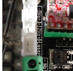
Yup, the LASER is a control port not a power connection.
More confusion.
In the layout docs that connector is labeled 12 [strange symbol] 24V
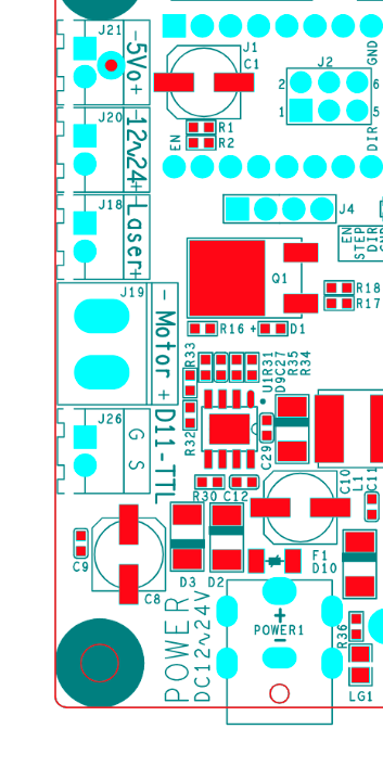
on your its:
Yup, the LASER is a control port not a power connection.
More confusion.
In the layout docs that connector is labeled 12 [strange symbol] 24V
on your its:
Don, I suspicious that there is a tactical issue with this.
Expecting to be able to run 10 amps through circuit board size traces, is asking for an issue. I’ve done circuit boards and the trace width becomes very large at even low currents, such as 5 amps.
I went to the digikey trace width calculator.
At 5 amps, 6mm (about 1/4") long, including a 5 C increase in temperature, on 1 oz pcb. The trace needs to be almost 11mm wide to carry that amount of current.
IMHO: I think that some part of that board is going to be the fusible link.
I’ve always run mine with a separate supply.

Well, since doing that (running the laser supply from the PSU directly) is not a problem then that’s what I’ll do.
Thinking about the issue of the laser coming on at power-up…isn’t it the case that pwm=0v means the laser will be off (yes, the fan will spin up, but it won’t actually lase until pwm>0v) ?
I would not expect it to be 10 amps? ![]()
I would guess more like 2- 4 amps.
There is also a fuse on that board.
To be sure one would have to inspect the land areas from input to the connector.
In systems designed for laser safety, I do not trust my eyes to software and electronics. Experience has taught me not to trust software and hardware design where I cannot see code and schematics for myself.
I would not assume the PWM asserts to 0 before the 12V comes up. Although it should, I would not trust the controller to hold PWM at 0 during POR.
Lack of manual control of the laser’s power also assumes that the driver software will never activate nor leave a job running without you asserting or knowing it has been left on.
I don’t like [and neither do laser safety stds] conditions where the laser can be on without you knowing or deliberately enabling it.
I have already seen one case where VigoWorks left the laser on when it crashed.
Also when enabled there should be a clear indication that the system is UNSAFE.
I plan to have a Laser Enable Switch, interlocks, and flashing strobe light added to my system that is in the 12V circuit. In addition, the user will be optically shielded from light exposure.
Thanks Don,
yes, that seems to be good sense. I’ll revert to plan B - connect the laser to the PSU through a switch.
Now I’ll start building the enclosure (I’m making it out of sheets of plexiglass and I didn’t want to start cutting and joining until I was sure about what was going where within the box. Having now decided, I can include a hole for the switch,attach the PSU and controller to the back rail of the frame, then cut the wires to length - just to make it all neat and tidy.
Ran the calculator at 5 amps and it was just under 11 mm trace width and it was only 1/4" (6mm) long.
You’re probably right if it has a fuse, that would give you a good idea of it’s limits.
BTW I found this module from NEJE [who are fast becoming my favorite laser vendor].
I am thinking about adding it in series with my laser to measure temperature, voltage, and PWM.
I have not yet evaluated it so I do not know if it works as advertised or if it has any compatibility problems.
Depending on the laser’s interface you may have to modify the connections.
I am also not sure the temp measurement is compatible with non NEJE lasers.
I’m also looking for some better documents on its operation.
It worthwhile to do a NEJE keyword search on Amazon.
Neat, that’s why we buy this junk… I have a pair of their lasers. They were really what peaked my interest, then fell for the co2 addiction. Have no complaint with them.
Can’t build it for you can buy it for…
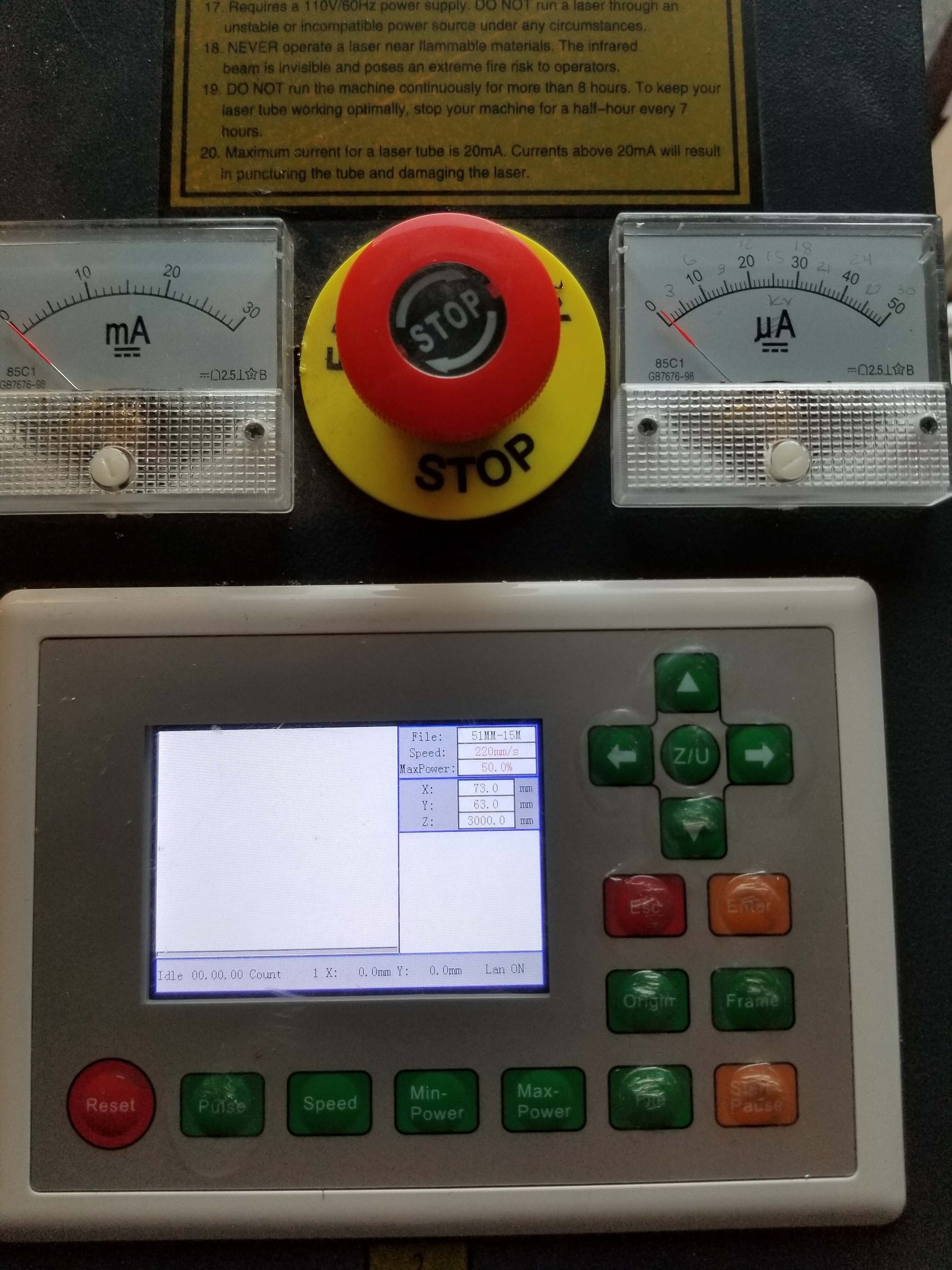
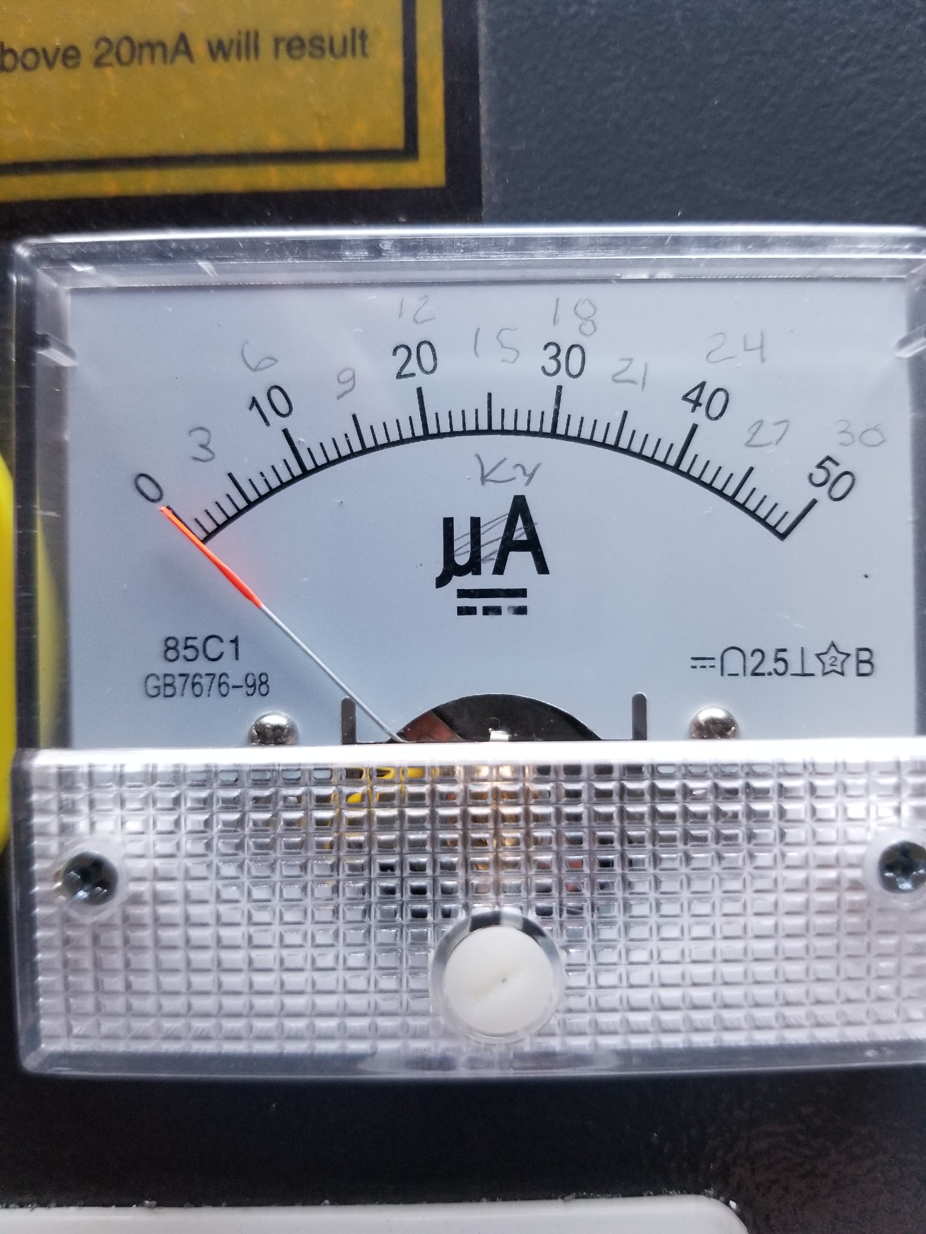
@donkjr got my high voltage meter installed… still isn’t finished, but working.
Meter…
Have a video here, < minute, but it’s pretty poor… early run 
“… got my high voltage meter installed…”
Be interested in how you implemented the hv meter.
Spoke to @mcdanlj about it and he advised I put it up when it’s working. But it isn’t completed.
Here is a link to my Google drive directory with a few photos. Give it a browse and let me know what you think…
If I post this, where would be the best place? Under hardware or?
What I was saying was to post publicly rather than in DMs, finished or not. I’ve posted lots of projects under constructions. Some have been failures. 
Sorry, it wasn’t finished, so I was dragging my feet. It hasn’t gone up in smoke, but in reality it’s a resistor with a meter to ground. How complicated could that part of it be?
I was wondering where I should post it, just ‘Laser Engravers/Cutters’?
Interesting to watch the change in hv when it changes pwm.
Posted some items at
Any questions?
![]()
Does that mean that one side of the meter is at HV?
No, the meter is between ground and the low-voltage end of the HV resistor stack. The neon bulb is so that if the connection between the meter and ground is interrupted, the low-voltage end of the HV resistor stack stays reasonably low (~90V) instead of ~20,000V
Exactly… the theory…
Did you see the video?
Hey I am a guy that never posts in these forums, but to day I found an impossible answer and it is rite here. One little diagram is all it took. No tech notes that I do not understand, just a simple sketch.
Thanks a lot Don, worked like a charm.
Glad we could help what diagram is it that helped you…
Don
It was the one posted in your message referring to hooking the 3 wire laser to the MKS DLC V.2 board.
Thanks again… works great NO SMOKE (: