@cprezzi , @Todd_Fleming since there is a feed rate and speed override available can we also get a PWM period/frequency over ride on the fly as well? Adjustments to this can dramatically change the end result much like feed and speed over rides… I shall do a bit of testing on the resulting image/cut quality with different pwm periods I am just asking if it is a possibility to add the feature before wasting much test time, thanks fellows 
in smoothie M221 S50 will set the PWM to 50% , it is a live setting and happens instantly on the current cut.
+Peter van der Walt agreed… I was thinking more of an advanced settings tab for config to really dial in the results you want I ran into some issues trying to help someone trouble shoot image engraving after they switched to a Lightobject PSU that was ment for a dsp. I do know that on the larger lasers pwm period/frequency is a setting when you are setting up your work and can make a load of difference when working with products like ceramark on stainless and aluminum
ahh frequency not duty cycle… ok. What is the normal frequency used for K40? Off topic my K40 seems to be ignoring the PWM duty cycle totally. M221 S10 is the same as M221 S100 as far as I can see WRT power. the meter does not drop and the burn looks the same. I currently run at 20KHz I think.
Side note @Wolfmanjm . One of my customers is experiencing the same issue with his machine that you just described - we confirmed that my board is outputting various PWM values as expected, but the laser only fires at one power level regardless. We tried both methods of wiring the pwm including replacing the pot/ and keeping the pot and simply pulsing L. So if this is indeed a K40 issue you are not alone.
mine is the 2-wire into L. I have not tried different frequencies.
Using multiple posts:
-
@raykholo I have many K40 users running L control and not a single one has a problem, including me. The one we are working on, I am pretty sure has a wiring problem or cockpit error in how the PWM control is asserted. Not your board and not the L connection.
-
If you are connected to the “IN” pin in any manner ALL BETS ARE OFF. This connection will work… but …WILL NOT … give you rational power control from the driving software. Do I hear an echo?
 I have completed plenty of research to prove this and gutted LPS’s to check their interfaces and control electronics. The testing I have done matches the theory all the way to the input of the LPS. Actual laser output measures are incomplete but initial results support the above assertion .
I created lots of posts on this subject
@Alex_Krause I can logic why variable PWM period control might be necessary as power and speed are changed if the basic power control schema is wonky (technical term) or does not have the response needed for proper operation. I have learned that with these machines there are configurations where pots are used to account for speed and laser variations or just poor control design.
What is the correct PWM schema? I have not completed my practical analysis and testing but here are principles I assert:
- The PWM frequency has to be fast enough to have the granularity needed to control a single pixel at the lowest power DF considering the speed of the gantry. Example: You want to be able to assert the PWM at a 90% duty cycle during a particular pixel time but 10% in the next pixel time. If the period of the PWM is to long the surface will see an overlap in power levels across a series of pixels. Therefore period and speed are related and matter. There is some max speed at which one will exceed the ability of the system to control properly.
- The period of the PWM cannot be so fast that the smallest DF results in a pulse that is shorter than the laser & LPS can respond. My initial measurements suggest that laser response times are in a 2-20us range.
- The actual PWM signal seen at the supplies output in our systems are the concatenation of two PWM controls. The LPS PWM and the controller PWM. In effect the L signal turns the internal PWM on and off. Therefore the relative period of these PWM’s will matter.
- The variables in this system are at least laser max power, gantry speed, and controller PWM period.
So what now?
– I am at the point that I can measure (I think) the input and output of this control system.
– I am pretty sure that the laser has an adequate response for the specified speeds range of the machine.
– I do not yet know but I can measure (when I get to it) the LPS internal PWM.
– I am building a calculator that takes all of the above into account and tells us what the operating frame for this machine is.
Yah, more questions than answers but getting the questions established helps get to the best schema.
All of the above said, unless the machine is set up in a way that the speed or power is outside of it operational limits then the the ability to control power, albeit irrationally, should exist.
If you are getting a beam but cannot control its power, and you are controlling from L, try slowing down the gantry and see if you get power changes at the surface.
The only way that we are going to get this machines power control schema understood is to build a model and then rationalize it with some input /output tests.
I am looking for a good way to create an input test pattern from the software on which I can stably sync my scope on a particular place on the image so that I can look at PWM vs power output.
It may very well be that in the end we do need “pots” to get optimum performance. But even if we do we will need to know how to implement them
All thoughts from the,
Square Peg…
@donkjr What frequency do you run your PWM into L at? I am wired as per your blog, 2.4 ground of mosfet to the L pin on PSU. running at 20KHz PWM. I tested the same circle at the same speed one at M221 S10 and one at M221 S100 and they were identical. even though there was supposed to be 10x difference in the requested power output (/PWM duty cycle). I have the pot connected and set to 10 mA so as to not wear out the tube  I also see no change in the meter reading when I do M221 S10 ( I would expect it to drop to 1ma unless I misunderstand how the PWM is supposed to be interpreted). WHen I got this the original board was using the L input for the laser control the other inputs were not connected to the M2 board at all. (I do not know if the M2 boards actually do power control or simple on/off)
The M2Nano simply turns L full on or full off, it does not have any pwm capability. So people using that are only able to set 1 power level for the entire job via the pot.
@raykholo how do you know that, has L been measured? How is engraving done, by dither? Never paid attention to if it grey shades or not before I trashed that controller?
When you say “people using it” do you mean in stock machines or when feeding L PWM?
+Peter van der Walt makes sense… but does not change our situation.
@donkjr Do you still want me to send you the PSU that I had the stepper cap pop? The Laser Side runs run and actually the stepper side still works. Just probably not as efficiently.
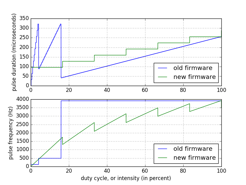
+Peter van der Walt Lasersaur PWM output is best summarized here (blue line): http://log2.ch/misc/laser/raster-testing/intensity-mapping.png
The PWM frequency is selected depending on the PWM duty (shown on the x-axis, set by gcode). The non-smoothness is just an implementation detail (timer prescale). The output is wired to the pin which enables the laser PSU (not the IN pin which supports PWM) - I thought was wrong but maybe it isn’t, and it works fine.
In my version of the firmware I’m using raster bytes to control each pulse duration. For light engraving I’m always limited by the minimum pulse duration, and just dithering (pulse or no pulse) works great.
@Joe_Spanier you mean a laser power supply … yes that would be awesome. What color connectors does it have?
@Martin_Renold man, I need to think about that approach.
PWM frequency is adjusted as a function of the demanded DF?
As the required DF gets larger the PWM frequency gets higher meaning that the PWM period is lower meaning that the time the laser is on is effectively lowered?
Am I understanding this right?
So the “actual” power vs the required DF is non-linearly adjusted downward?
Thinking … and my head hurts.